Holographic waveguide optical tracker

Active Publication Date: 2018-08-16
DIGILENS
View PDF4 Cites 110 Cited by
  • Summary
  • Abstract
  • Description
  • Claims
  • Application Information

AI Technical Summary

Benefits of technology

The invention is a transparent tracker with low latency and a wide field of view for tracking the movement of objects and people. It can be used in eye-slaved displays, which provide realistic depth and occlusion cues, to create a more immersive visual experience. The tracker can also be integrated into a LIDAR system. Overall, the invention provides a compact and efficient solution for tracking and display technology.

Problems solved by technology

The first practical challenge is how to introduce the image sensor and illuminator in such a way that both can work efficiently while avoiding obscuring the line of sight Most eye tracker implementations in HMDs have employed flat beam splitters in front of the users' eyes and relatively large optics to image the reflections onto an imaging sensor.
In order to maximize the exit pupil, the imaging optics are positioned close to the beamsplitter, and represent a vision obscuration and a safety hazard.
Another known limitation with eye trackers is the field of view, which is generally limited by the illumination scheme in combination with the geometry of the reflected images.
The size of the corneal reflected angles would ordinarily require a large angular separation between the illumination and detection optical axes making using corneal reflections over large FOVs very difficult.
However, the latency incurred by the need to recognize and track eye features remains a significant processing bottleneck.
Although recent advances in displays have collectively spanned these requirements no one display technology possesses all of these characteristics.
The device exhibits near 100% efficiency with no voltage applied and essentially zero efficiency with a sufficiently high voltage applied.

Method used


Image

  • Holographic waveguide optical tracker
  • Holographic waveguide optical tracker
  • Holographic waveguide optical tracker

Examples


Embodiment Construction

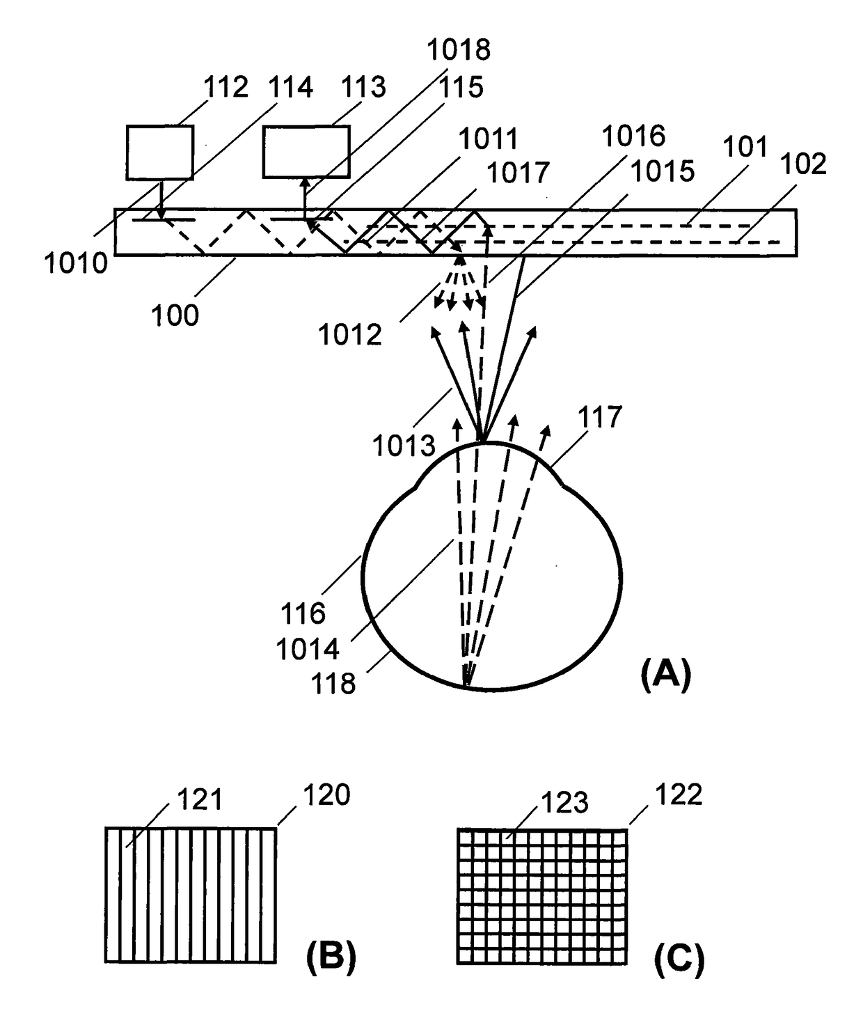
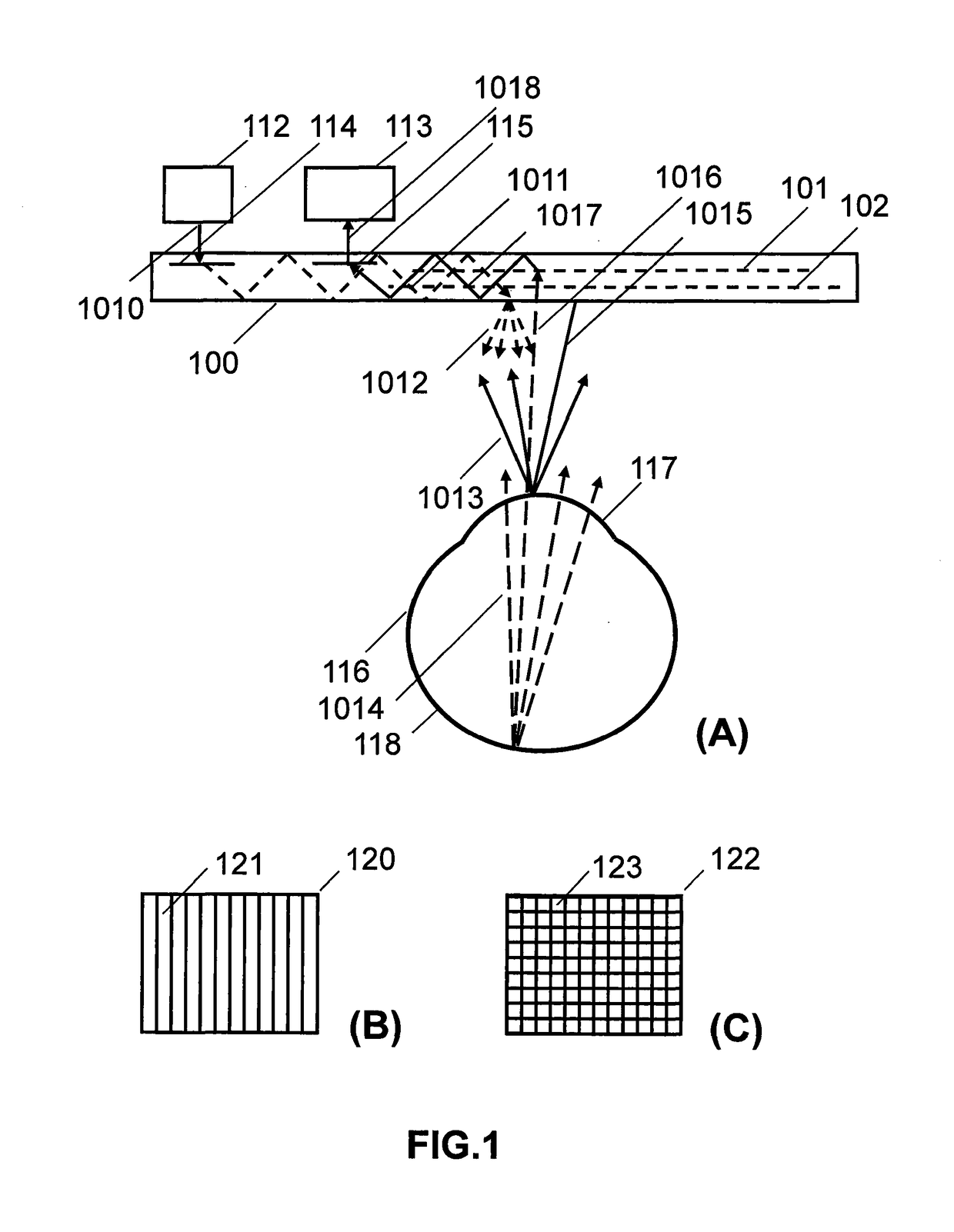
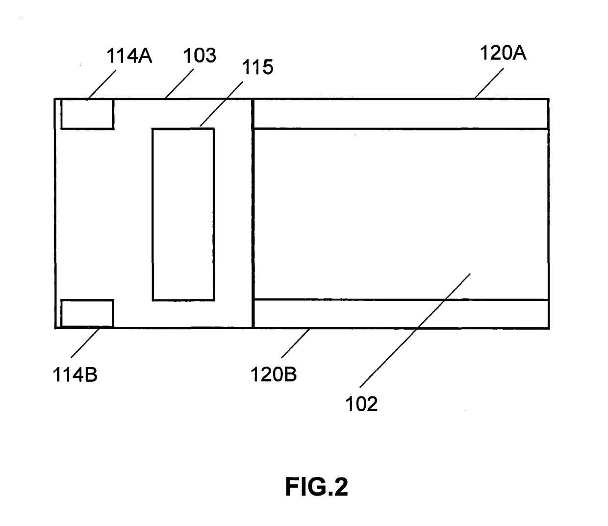
[0164]The invention will now be further described by way of example only with reference to the accompanying drawings. It should be apparent to those skilled in the art that the present invention may be practiced with some or all of the present invention as disclosed in the following description. For the purposes of explaining the invention well-known features of optical technology known to those skilled in the art of optical design and visual displays have been omitted or simplified in order not to obscure the basic principles of the invention. Unless otherwise stated the term “on-axis” in relation to a ray or a beam direction refers to propagation parallel to an axis normal to the surfaces of the optical components described in relation to the invention. In the following description the terms light, ray, beam and direction may be used interchangeably and in association with each other to indicate the direction of propagation of electromagnetic radiation along rectilinear trajectori...


PUM


Abstract

There is provided an object tracker having: a first waveguide; a source of illumination light; a detector optically coupled to the waveguide; and at least one grating lamina formed within the waveguide. Illumination light propagating along a first optical path from the source to an object in relative motion to the object tracker. Image light reflected from at least one surface of an object is deflected by the grating lamina into a second optical path towards the detector.

Description

PRIORITY CLAIMS[0001]This application claims priority from U.S. Provisional application Ser. No. 62 / 071,534 filed on 26 Sep. 2014, 62 / 124,154 filed on 10 Dec. 2014, 62 / 125,454 filed on 22 Jan. 2015, and 62 / 179,336 filed on 5 May 2015, each of which is hereby incorporated by reference in its entiretyCROSS REFERENCE TO RELATED APPLICATIONS[0002]The following patent applications are hereby incorporated by reference herein in their entireties: U.S. patent application Ser. No. 13 / 506,389 entitled COMPACT EDGE ILLUMINATED DIFFRACTIVE DISPLAY, U.S. Pat. No. 8,224,133 entitled LASER ILLUMINATION DEVICE, U.S. Pat. No. 8,565,560 entitled LASER ILLUMINATION DEVICE, PCT / GB2013 / 000210 entitled APPARATUS FOR EYE TRACKING, U.S. Pat. No. 6,115,152 entitled HOLOGRAPHIC ILLUMINATION SYSTEM, U.S. Pat. No. 8,233,204 entitled OPTICAL DISPLAYS, PCT Application No.: GB2013 / 000210 entitled APPARATUS FOR EYE TRACKING, PCT Application No.: US2006 / 043938, entitled METHOD AND APPARATUS FOR PROVIDING A TRANSPAR...

Claims


Application Information

Patent Timeline
IPC IPC(8): G06F3/01G02B27/00G02B27/01G02B6/10
CPCG06F3/013G02B27/0093G02B27/0172G02B6/105A61B3/113G02F1/2955G02B6/0016G02B27/017G02F2201/307A61B3/10
Inventor POPOVICH, MILAN MOMCILOWALDERN, JONATHAN DAVIDGRANT, ALASTAIR JOHNLOKIVIC, KIMBERLY SUN
Owner DIGILENS
Why Eureka
Try Eureka