Polymer composition, article, medical device, article production method, and cell cluster production method

Active Publication Date: 2018-08-09
JSR CORPORATIOON +1
View PDF5 Cites 3 Cited by
  • Summary
  • Abstract
  • Description
  • Claims
  • Application Information

AI Technical Summary

Benefits of technology

The present invention provides a medical device that is easy to use and durable. Additionally, a cell adhesion inhibitor is provided that is not harmful to cells and can prevent them from attaching to surfaces. This invention also allows for the production of cell clusters and a silicone substrate treatment composition that has excellent hydrophilicity and can prevent the adhesion of sample components, particularly biological samples. Furthermore, a silicone substrate production method is provided that allows for the creation of a substrate that is resistant to the adhesion of biological samples.

Problems solved by technology

However, conventional surfaces generally exhibit low lubricity upon coming into contact with a biological tissue or the like and have poor hydrophilicity; therefore, such conventional surfaces may cause problems such as deterioration of a medical device due to friction, inflammation of a living body, and the like.
Such cell adhesion presents problems in various fields, including the medical field.
The occurrence of such cell adhesion in a medical equipment, an apparatus or the like in this manner creates major problems since it not only simply causes contamination but also results in, for example, clogging and reduction in analysis accuracy and sensitivity.
However, since the channels of such microchannel devices are narrow, there is a problem that adhesion of a biological sample or the like to the channel surface is likely to cause a reduction in flow rate.
In addition, adhesion of a sample component to the channel surface makes the channel even narrower, and the effects of the loss of a reagent or the like on measured values are not negligible.
Furthermore, since silicone rubber substrates have a low affinity for water, when a liquid including water is allowed to flow in the channel, poor fluidity potentially makes it impossible to accurately perform a desired operation.

Method used


Image

  • Polymer composition, article, medical device, article production method, and cell cluster production method
  • Polymer composition, article, medical device, article production method, and cell cluster production method
  • Polymer composition, article, medical device, article production method, and cell cluster production method

Examples


synthesis example 1

Synthesis of Copolymer (N-1)

[0390]In a flask, 8.5 g of methoxypolyethylene glycol (23) monomethacrylate (M-230 G (manufactured by Shin-Nakamura Chemical Co., Ltd.); hereinafter, referred to as “MPEGM”. It is noted here that “polyethylene glycol (23)” means “(OC2H4)23”, and the same applies hereinbelow), 0.25 g of NHmethacryloyloxyethyl-N,N-dimethylammonium-α-N-methylcarboxy betaine (GLBT (manufactured by Osaka Organic Chemical Industry Ltd.); hereinafter, referred to as “GLBT”), 1.25 g of lauroxypolyethylene glycol (30) monomethacrylate (PLE-1300 (manufactured by NOF Corporation); hereinafter, referred to as “LPEGM”), 0.1 g of 2,2′-azobis(isobutyronitrile) (manufactured by Wako Pure Chemical Industries, Ltd.; hereinafter, referred to as “AIBN”) as a polymerization initiator, and 27 g of pure water and 63 g of acetonitrile as a solvent were added and mixed together. Then, nitrogen was blown into the resulting mixture, and the mixture was heated to 60° C. and allowed to polymerize for...

synthesis example 2

Synthesis of Copolymer (N-2)

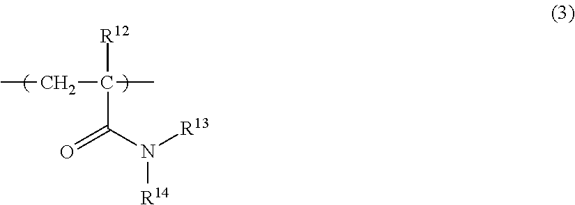
[0393]In a flask, 8.5 g of acryloyl morpholine (ACMO (manufactured by KJ Chemicals Corporation); hereinafter, referred to as “ACM”), 0.25 g of GLBT, 1.25 g of LPEGM, 0.1 g of AIBN, 27 g of pure water, and 63 g of acetonitrile were added and mixed together. Then, nitrogen was blown into the resulting mixture, and the mixture was heated to 60° C. and allowed to polymerize for 4 hours, after which the resultant was cooled to room temperature. Thereafter, the thus obtained solution was dialyzed with pure water, whereby an aqueous solution of a copolymer (N-2) was obtained.

[0394]In the thus obtained copolymer (N-2), the content of an ACM-derived repeating unit was 85° by mass; the content of a GLBT-derived repeating unit was 2.5% by mass; and the content of an LPEGM-derived repeating unit was 12.5% by mass.

[0395]Further, the thus obtained copolymer (N-2) had a weight-average molecular weight of 455,000, a number-average molecular weight of 137,000, and a molec...

synthesis example 3

Synthesis of Copolymer (N-3)

[0396]In a flask, 8.5 g of dimethylacrylamide (DMAA (manufactured by KJ Chemicals Corporation) ; hereinafter, referred to as “DMA”), 0.25 g of GLBT, 1.25 g of LPEGM, 0.1 g of AIBN, 27 g of pure water, and 63 g of acetonitrile were added and mixed together. Then, nitrogen was blown into the resulting mixture, and the mixture was heated to 60° C. and allowed to polymerize for 4 hours, after which the resultant was cooled to room temperature. Thereafter, the thus obtained solution was dialyzed with pure water, whereby an aqueous solution of a copolymer (N-3) was obtained.

[0397]In the thus obtained copolymer (N-3), the content of a DMA-derived repeating unit was 85% by mass; the content of a GLBT-derived repeating unit was 2.5° by mass; and the content of an LPEGM-derived repeating unit was 12.5° by mass.

[0398]Further, the thus obtained copolymer (N-3) had a weight-average molecular weight of 499,000, a number-average molecular weight of 125,000, and a molecu...


PUM

PropertyMeasurementUnit
Solubility (mass)aaaaaaaaaa

Abstract

The present invention relates to: a polymer composition; an article; a medical device; an article production method; and a cell cluster production method. The polymer composition contains a polymer having the following repeating units (A) and (B) and is one selected from the group consisting of a medical device composition, a cell adhesion inhibitor, and a silicone substrate treatment composition:(A) a hydrophilic repeating unit; and(B) a repeating unit which has a polyoxyalkylene group in a side chain whose terminal is constituted by an alkyl group having 5 to 30 carbon atoms, an alkanoyl group having 5 to 30 carbon atoms, or an aryl group having 6 to 30 carbon atoms.

Description

TECHNICAL FIELD[0001]The present invention (I) relates to: a medical device composition; a medical device; and a method of producing the same. Particularly, the present invention (I) relates to: a medical device composition capable of imparting excellent lubricity to the surface of a medical device; a medical device having a lubricant surface; and a method of producing the medical device.[0002]The present invention (II) relates to: a cell adhesion inhibitor; a cell culture equipment; a method of producing the equipment; and a method of producing a cell cluster.[0003]The present invention (III) relates to: a silicone substrate treatment composition; a silicone substrate; a silicone substrate having a microchannel; and a method of producing a silicone substrate.BACKGROUND ART[0004](I) In the medical field, medical devices that include a part coming into contact with a living body, such as catheters, tubes, endoscopes and insertion tools, are required to have a lubricant surface for in...

Claims


Application Information

Patent Timeline
IPC IPC(8): C08F220/34C08F220/28C08F216/12C08F299/08
CPCC08F220/34C08F220/28C08F216/12C08F299/08C12N5/0018A61L29/041A61L27/16A61L17/145A61L27/34A61L27/50A61L29/10A61L29/14A61L31/10A61L31/14A61L2400/10C08F220/20C08F220/54C08F226/10C09D4/00C09D133/26C08F220/286C08F220/365C08F230/02C08L83/04C09D133/14
Inventor HYUUGAJI, SATOSHI
Owner JSR CORPORATIOON
Why Eureka
Try Eureka