
Dynamic vision sensor architecture

a vision sensor and dynamic technology, applied in the field of vision sensors, can solve the problems of motion artifacts, large pixel circuits, delay in data readout from parts of the sensor, etc., and achieve the effect of less temporal jitter and easy design

Active Publication Date: 2018-07-05
SONY ADVANCED VISUAL SENSING AG
View PDF2 Cites 44 Cited by
  • Summary
  • Abstract
  • Description
  • Claims
  • Application Information

AI Technical Summary

Benefits of technology

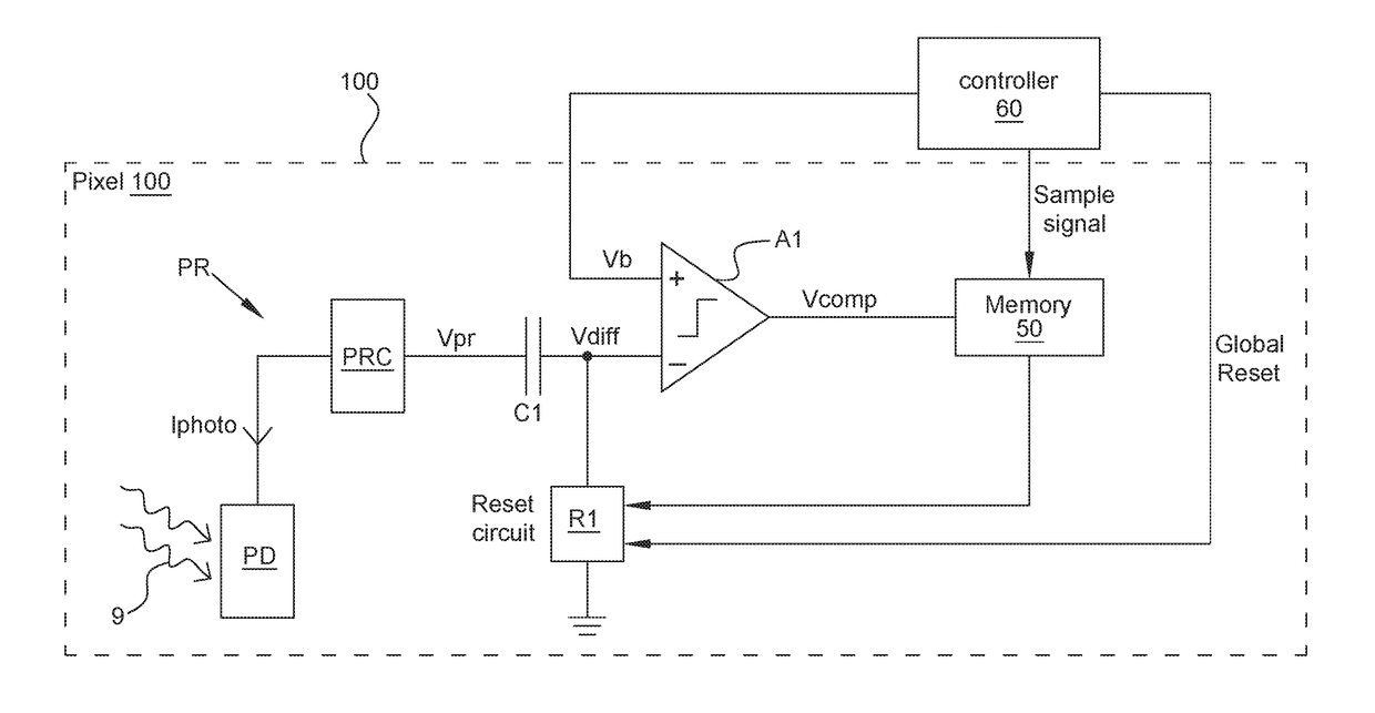
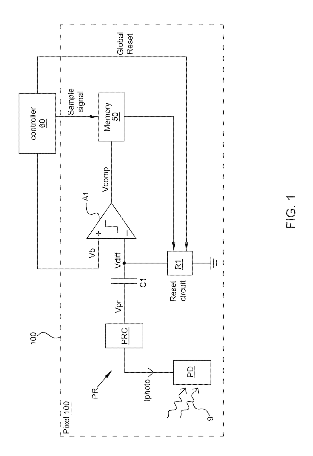
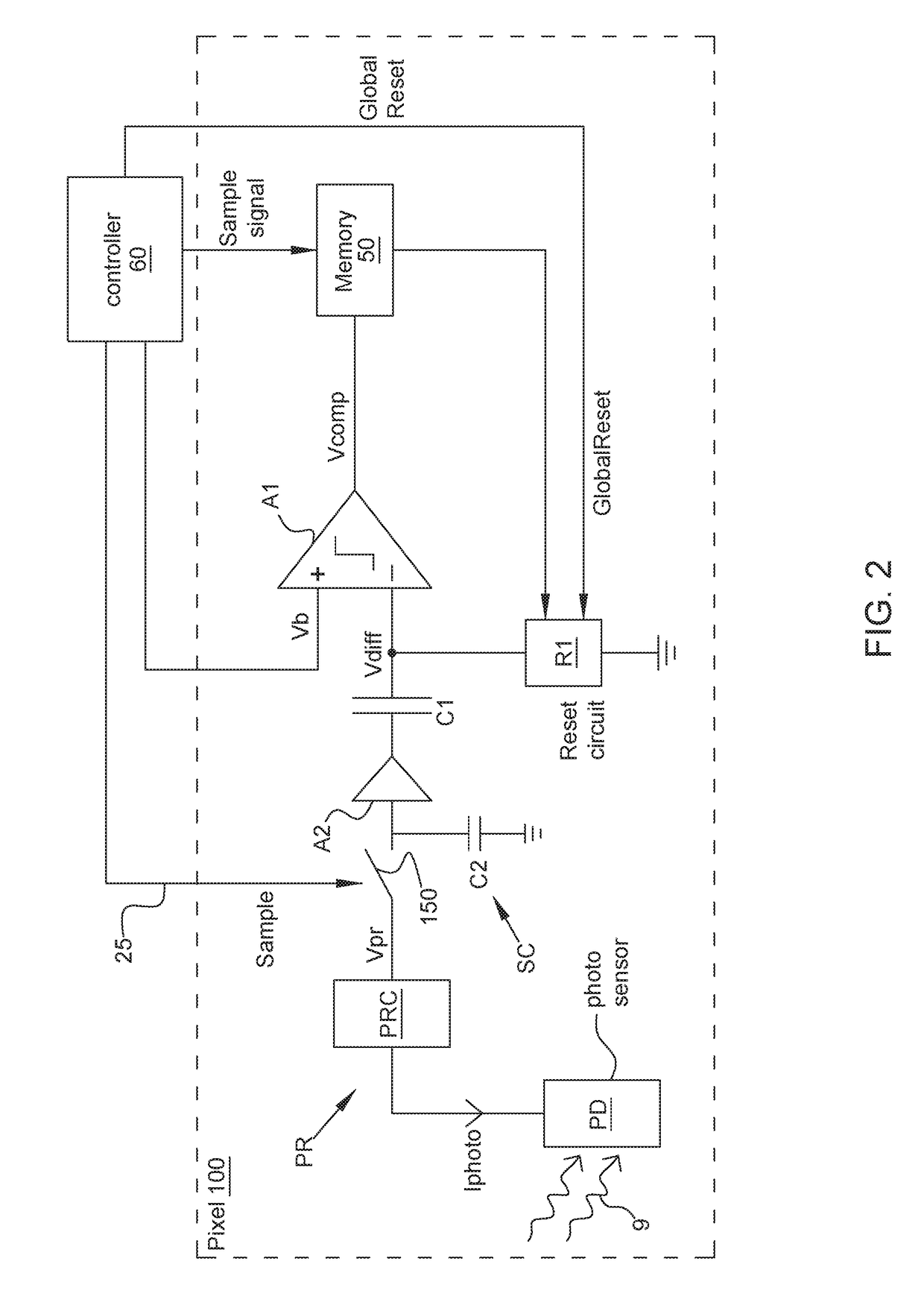
The invention removes comparators from the array of pixels, which reduces the size of the pixels and helps in avoiding motion artifacts caused by timing jitter. However, a few comparators can still be used for necessary thresholding functions. This helps in improving the overall performance of the readout circuit.

Problems solved by technology

1. Pixel circuits can be large because they include an amplifier and two comparators, in some cases.
2. Asynchronous readout circuits are prone to timing jitter. If large areas of the scene change in a short time, jitter increases and data readout from parts of the sensor can be delayed, leading to motion artifacts.
3. Because DVS pixels circuits tend to be self-timed, a sensor time resolution cannot be imposed, and very fast changes in a small area can saturate the communication bandwidth.

Method used


Image

  • Dynamic vision sensor architecture
  • Dynamic vision sensor architecture
  • Dynamic vision sensor architecture

Examples


Embodiment Construction

[0077]The invention now will be described more fully hereinafter with reference to the accompanying drawings, in which illustrative embodiments of the invention are shown. This invention may, however, be embodied in many different forms and should not be construed as limited to the embodiments set forth herein; rather, these embodiments are provided so that this disclosure will be thorough and complete, and will fully convey the scope of the invention to those skilled in the art.

[0078]As used herein, the term “and / or” includes any and all combinations of one or more of the associated listed items. Further, the singular forms and the articles “a”, “an” and “the” are intended to include the plural forms as well, unless expressly stated otherwise. It will be further understood that the terms: includes, comprises, including and / or comprising, when used in this specification, specify the presence of stated features, integers, steps, operations, elements, and / or components, but do not pre...


PUM


Abstract

A dynamic vision sensor (DVS) or change detection sensor reacts to changes in light intensity and in this way monitors how a scene changes. This disclosure covers both single pixel and array architectures. The DVS may contain one pixel or 2-dimensional or 1-dimensional array of pixels. The change of intensities registered by pixels are compared, and pixel addresses where the change is positive or negative are recorded and processed. Analyzing frames based on just three values for pixels, increase, decrease or unchanged, the proposed DVS can process visual information much faster than traditional computer vision systems, which correlate multi-bit color or gray level pixel values between successive frames.

Description

RELATED APPLICATIONS[0001]This application claims priority to Swiss Provisional Patent Application No. CH20160001764, filed on 30 Dec. 2016, and Swiss Provisional Patent Application No. CH20160001765, filed on 30 Dec. 2016, both of which are incorporated herein by reference in their entirety.FIELD OF THE INVENTION[0002]This invention concerns vision sensors and more particularly dynamic or change detection sensors. These sensors react to changes in light intensity and in this way monitor how a scene changes.BACKGROUND OF THE INVENTION[0003]Today, machine vision is mostly based on conventional cameras and their associated frame-based image sensors. For some machine vision tasks, e.g., object recognition, these conventional frame-based cameras are well suited. However, for other tasks, e.g., tracking or position and motion estimation, the conventional image sensors have drawbacks.[0004]The main drawback is that conventional cameras produce a significant amount of redundant and unneces...

Claims


Application Information

Patent Timeline
IPC IPC(8): H04N5/355H01L27/146
CPCH04N5/35518H01L27/1461H04N25/44H04N25/77H04N25/78H04N25/47G01J1/46H04N25/573H04N25/766H04N25/778H04N25/7795H04N25/75H04N25/40H04N25/772G06F11/004G06F2201/86G06F2201/88G06T7/20
Inventor BERNER, RAPHAELBRANDLI, CHRISTIAN
Owner SONY ADVANCED VISUAL SENSING AG
Learn More