
Electrocatalytic system for reducing pullution and fuel consumption

a technology of electrocatalytic system and fuel consumption, which is applied in the direction of electric control, machines/engines, lighting and heating apparatus, etc., can solve the problems of difficult to charge hybrid vehicles, and difficult to retrofit a regular fossil fuel vehicle with a hybrid system. achieve the effect of reducing fossil fuel consumption and emissions, reducing engine emissions, and reducing an amount of fossil fuel

Inactive Publication Date: 2018-06-21
SALEK FARHAD +4
View PDF0 Cites 8 Cited by
  • Summary
  • Abstract
  • Description
  • Claims
  • Application Information

AI Technical Summary

Benefits of technology

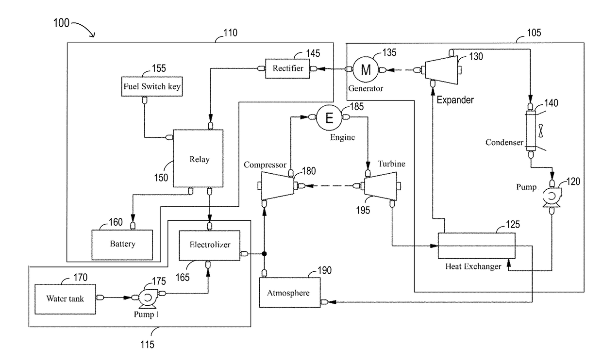
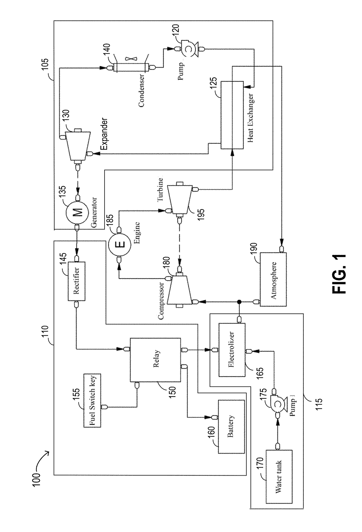
The patent describes a system that helps reduce fuel consumption and emissions in an engine. It does this by using waste heat to create steam, which is then converted into electricity. The electricity is stored in a battery. The system also includes a water electrolysis unit that uses the stored electricity to create hydrogen gas, which is then injected into the engine. This reduces the amount of fuel needed and helps reduce emissions.

Problems solved by technology

Although, this mechanism reduces emission and fossil fuel consumption, due to the complexity of the transmission lines in these vehicles, which are linked to two sources of power, it is very difficult to retrofit a regular fossil fuel vehicle with a hybrid system.
Additionally, hybrid vehicles are sometimes difficult to charge, particularly in public places, because charging stations for these vehicles are not yet commonly established.
Another disadvantage of hybrid vehicles is the rapid discharge of the systems' batteries.
However, such systems generally require electrical energy to be supplied to the electrode plates of the electrocatalytic systems.
This electric energy is often supplied by the vehicle's main battery which results in rapid discharge of the battery.
This in itself creates a source of energy inefficiency.
It has been established that vehicles often produce the most amount of pollutants when they are running on low speeds.
For example, when a bus stops at the bus station or vehicles are stuck in traffic or waiting behind a red light, they generate the most of amount of pollutants.
This means that, in one implementation, the system 100 achieves its best results when the system is activated while the vehicle is running at a slow speed (and low exhaust gas temperature) and producing increased pollutant emissions.

Method used


Image

  • Electrocatalytic system for reducing pullution and fuel consumption
  • Electrocatalytic system for reducing pullution and fuel consumption
  • Electrocatalytic system for reducing pullution and fuel consumption

Examples


Embodiment Construction

[0016]In the following detailed description, numerous specific details are set forth by way of examples in order to provide a thorough understanding of the relevant teachings. However, it should be apparent to those skilled in the art that the present teachings may be practiced without such details. In other instances, well known methods, procedures, components, and / or circuitry have been described at a relatively high-level, without detail, in order to avoid unnecessarily obscuring aspects of the present teachings. As part of the description, some of this disclosure's drawings represent structures and devices in block diagram form in order to avoid obscuring the invention. In the interest of clarity, not all features of an actual implementation are described in this specification. Moreover, the language used in this disclosure has been principally selected for readability and instructional purposes, and may not have been selected to delineate or circumscribe the inventive subject m...


PUM


Abstract

An improved electrocatalytic system utilizes an Organic Rankine cycle system to take advantage of exhaust fume heat to convert a working fluid to steam used in a steam expander to generate electricity. The generated electricity is then used in electrolyzing water to produce hydrogen gases used as a supplemental fuel in an internal combustion (IC) engine. Thereby, the improved electrocatalytic system provides an efficient, less costly and retrofittable system for reducing harmful emissions and fossil fuel consumption in vehicles.

Description

CROSS REFERENCE TO RELATED APPLICATION[0001]This application claims the benefit of priority to Iran Application Serial Number 139550140003014638, filed on Feb. 17, 2017, the entire content of which is incorporated herein by reference.TECHNICAL FIELD[0002]This subject matter relates generally to converting exhaust fume heat to electricity in an internal combustion engine, and more particularly to generating hydrogen from the energy of engine emissions in existing internal combustion engines while minimizing engine retrofitting and reducing engine emissions.BACKGROUND[0003]Great efforts have been spent in recent years in developing system that reduce the amount of fossil fuel consumption and harmful emission of internal combustion (IC) engines. Hybrid vehicles are one of such systems. In hybrid vehicles, a high-power electric motor is used along with an IC engine for power. The IC engine helps charge the electric motor which is in turn used to drive the vehicle for some distance befor...

Claims


Application Information

Patent Timeline
Patent Type & Authority Applications(United States)
IPC IPC(8): F02C6/18F02D41/00F02D19/06F02B47/02
CPCF02C6/18F02D41/0027F02D19/0671F02D19/066F02D19/0644F02B47/02F22B1/1815F25B27/02F01N5/02F02B2043/106F01K23/10F01N3/01F01N2240/02F01N2900/1631F02D41/0025F02D2200/604F02G5/02Y02T10/12Y02T10/30
Inventor SALEK, FARHADSAFARI, MOHAMMAD REZANASERIAN, MOHAMMAD MAHDIMOGHADDAM, ALIREZA NAGHAVIJAHANTIGH, ALIREZA
Owner SALEK FARHAD
Learn More