Improved components of a fluid transfer apparatus

Active Publication Date: 2018-06-14
EQUASHIELD MEDICAL
View PDF2 Cites 15 Cited by
  • Summary
  • Abstract
  • Description
  • Claims
  • Application Information

AI Technical Summary

Benefits of technology

The invention is a connector component that prevents fluids from entering or exiting the needles when it is not connected to any other component of a fluid transfer system. The connector has arms with rounded rear sides that are engaged in sockets at the distal open end of an outer housing. The tips of the needles are isolated from the outside, creating a tight seal. The connector also has independent guiding channels for each arm and enlarged element, which prevents deformation of the outer housing or guiding channels due to forces applied by the enlarged elements.

Problems solved by technology

One extremely demanding application exists in the field where medical and pharmacological personnel that are involved in the preparation and administration of hazardous drugs suffer the risk of being exposed to drugs and to their vapors, which may escape to the surroundings.
Since hazardous drugs are toxic, direct bodily contact thereto, or exposure to even micro-quantities of the drug vapors, considerably increases the risk of developing health fatalities such as skin cancer, leukemia, liver damage, malformation, miscarriage and premature birth.
Such exposure can take place when a drug containing receptacle, such as a vial, bottle, syringe, and intravenous bag, is subjected to overpressure, resulting in the leakage of fluid or air contaminated by the hazardous drug to the surroundings.
When part of the liquid does accidently find its way into the air chamber of the syringe, in addition to the obvious problems of esthetics, additional time consuming working steps become necessary to retrieve the drug and correct the dosage.
At such a time the piston rod might be accidentally pushed causing some of the drug to migrate to the proximal air chamber above the piston from where it cannot be expelled from the syringe.
In such case the plunger needs to be pulled back in order to retrieve the drug, which is an extra work step and the wet residuals in the air chamber 32 cause an aesthetic problem.
In these situations, accidental pushing on the piston rod to return liquid or bubble to the vial will also cause some liquid to be forced through the air channel into the air chamber in the syringe.
The way to remove the bubble is a relatively time consuming and complex procedure involving disconnecting the syringe from the vial and reconnecting it.
Special attention is required to avoid pushing the plunger accidentally, which slows down the speed of work.
Such isolation of the needles constitutes a design challenge.
Such accidental pushing, which (as a side note) is very common, does not create high pressure inside the double membrane seal actuator since there is free flow from chamber to chamber and high pressure cannot be maintained and collapses immediately until equilibrium is reached.
Therefore the sealing properties of the elements in the actuator are never challenged with high pressure and moderate design is sufficient.
Under such pressures most of the isolation designs between the needles will fail and drug will be transferred to the air chamber or even worse, the membranes 34a and 34b cannot resist high pressures, which can cause them to detach from their seat or can cause a leak through the channels in the membranes that were created by the needles during piercing the resilient material of the membrane.
This can happen, for example, if pressure differentials between the air and liquid chambers exist after disconnection from a vial adapter and if the pressure in the air chamber is lower than that in the liquid chamber, resulting in undesired migration of liquid to the air chamber.
A common problem associated with the procedure is that during the trip from pharmacy to ward or at bedside the piston of the syringe is sometimes unintentionally pushed expelling some of the drug from the barrel of the syringe or the piston is unintentionally pulled.
Such pressure may cause the connector to disintegrate or the membranes to be detached.

Method used


Image

  • Improved components of a fluid transfer apparatus
  • Improved components of a fluid transfer apparatus
  • Improved components of a fluid transfer apparatus

Examples


Embodiment Construction

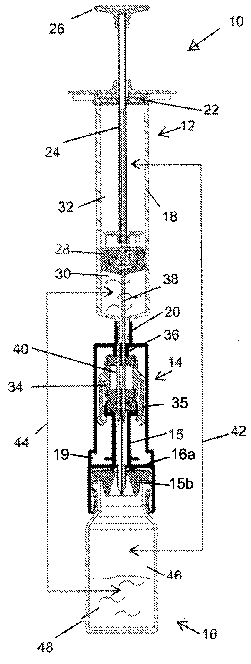
[0095]The present invention is improved versions of some of the components of the fluid transfer apparatuses described in the background section of this application. FIG. 8a schematically shows fluid transfer apparatus 100 in which are incorporated the improvements of the present invention.

[0096]Apparatus 100 comprises a first component—in this case syringe 102, a connector component 104, an adapter component 106 to allow connection of connector component 104 to a second component—in this case vial 108.

[0097]The changes that have been made to apparatus 100 relative to the prior art and which will be described in detail below are the following:[0098]the elements that seal the proximal end of the syringe 102 have been redesigned resulting in an improved syringe;[0099]the arms on the septum holder in the connector component 104 have been redesigned and the way in which they move in order to carry out their function has been changed;[0100]the exterior and interior of the outer housing o...


PUM


Abstract

Described are improvements to components of fluid transfer apparatuses comprising a first component, e.g. a syringe, a connector component configured to connect between the first component and an adapter component that is configured to allow connection of the connector component to a second component of the drug transfer apparatus, e.g. to a drug vial. The improvements include inter alia changes to the sealing elements that seal the proximal end of the syringe, redesign of a septum holder inside the connector component and corresponding redesign of the housing of the connector component; changes to the structure of the end of the connector component that connects to the first component to allow the first component to swivel relative to the connector component; and changes to the design of the adapter component to a second component of the drug transfer apparatus to allow it to mate with the redesigned housing of the connector component.

Description

FIELD OF THE INVENTION[0001]The present invention relates to the field of fluid transfer apparatuses. Particularly, the invention relates to apparatus for the contamination-free transfer of a hazardous drug from one container to another or to a patient. More particularly, the invention relates to improvements to syringes and to connectors and adapters that are used in fluid transfer apparatuses.BACKGROUND OF THE INVENTION[0002]Advances in medical treatment and improved procedures constantly increase the need for improved valves and connectors. The demands relating to variety of types, quality, needle safety, microbial ingress prevention and leak prevention are constantly growing. Additionally, advances in sampling or dose dispensing technologies, automated and manual, aseptic or non-aseptic applications, call for new safe concealing solutions for the sampling needle. One extremely demanding application exists in the field where medical and pharmacological personnel that are involved...

Claims


Application Information

Patent Timeline
IPC IPC(8): A61J1/20A61J1/14A61J1/10A61M5/14
CPCA61J1/2096A61J1/1406A61J1/201A61J1/2055A61J1/2065A61J1/10A61M5/1413A61M5/3135A61M5/31A61M39/10A61M2005/3121A61M2005/3101A61M2039/1077A61J1/1481A61J1/00
Inventor KRIHELI, MARINO
Owner EQUASHIELD MEDICAL
Why Eureka
Try Eureka