
Manufacturing method of circuit board and structure thereof

a manufacturing method and circuit board technology, applied in the direction of printed circuit manufacturing, printed circuit aspects, printed circuit, etc., can solve the problems of difficult manufacturing of metal circuit layers, increased material and production costs required for printing circuit boards, and reduced production efficiency of printed circuit boards. , to achieve the effect of small line width, line spacing, and reduced second patterned circuit layers

Inactive Publication Date: 2018-06-07
UNIMICRON TECH CORP
View PDF0 Cites 0 Cited by
  • Summary
  • Abstract
  • Description
  • Claims
  • Application Information

AI Technical Summary

Benefits of technology

The invention relates to a method of manufacturing a circuit board. The method involves forming a patterned circuit layer on a circuit substrate, followed by adding a patterned glue layer on top of the circuit layer. Next, a second patterned circuit layer is formed on top of the glue layer using a transfer-printing method. This results in a final circuit board that has two patterned circuit layers formed using different methods. The second patterned circuit layer has narrower lines and closer spacing with the first patterned circuit layer, which allows for a more compact and efficient circuit design.

Problems solved by technology

However, the aforementioned process requires high investment in equipments and materials, such that the material and production costs required for the manufacturing process of printing the circuit board are greatly increased.
Additionally, a thick metal circuit layer (e.g., a thick copper layer) is difficult to be manufactured by the aforementioned modified semi-additive process, such that the application of the thick metal circuit layer in the production of the thin circuit structure is restricted.

Method used


Image

  • Manufacturing method of circuit board and structure thereof
  • Manufacturing method of circuit board and structure thereof
  • Manufacturing method of circuit board and structure thereof

Examples


Embodiment Construction

[0021]In the following detailed description, for purposes of explanation, numerous specific details are set forth in order to provide a thorough understanding of the disclosed embodiments. It will be apparent, however, that one or more embodiments may be practiced without these specific details. In other instances, well-known structures and devices are schematically shown in order to simplify the drawing.

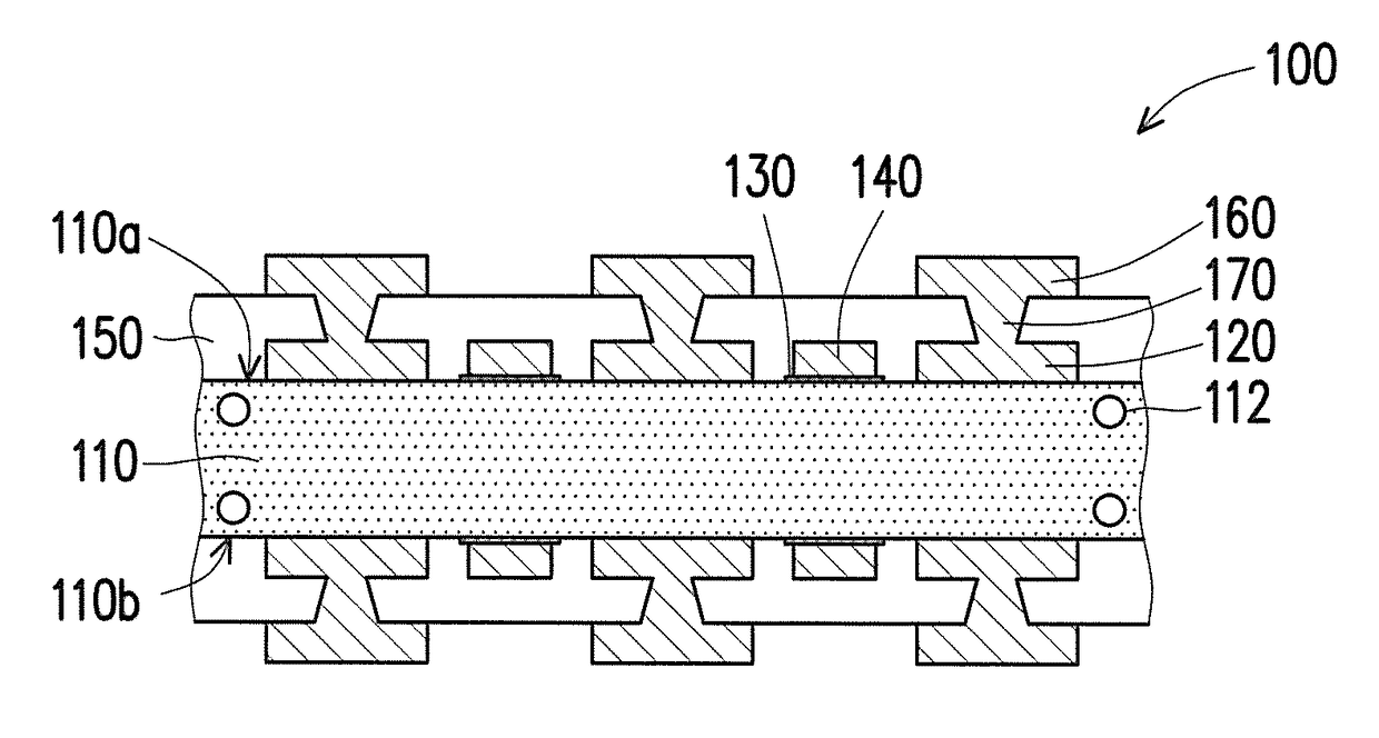
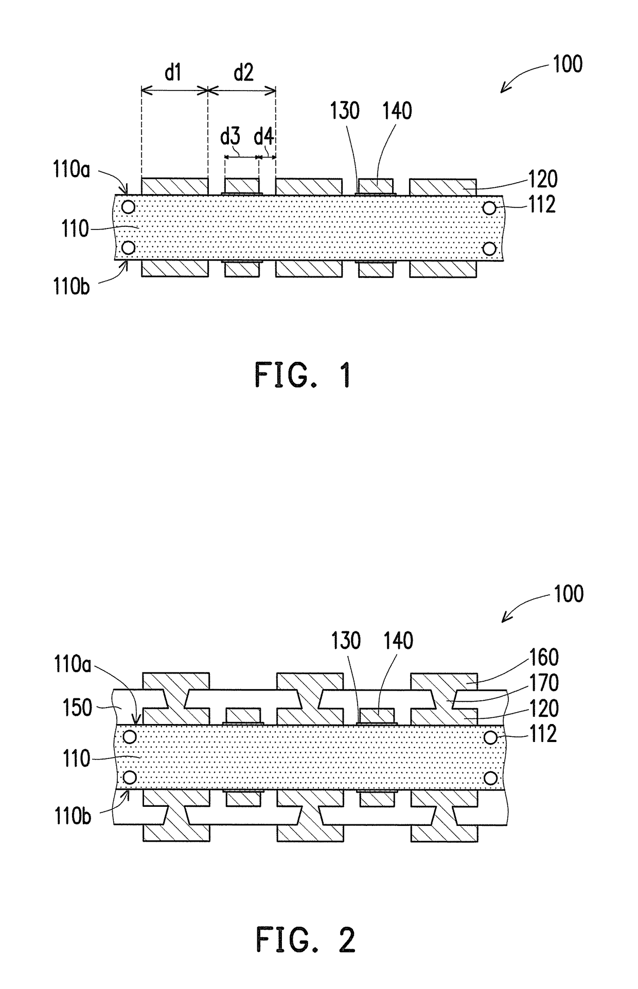
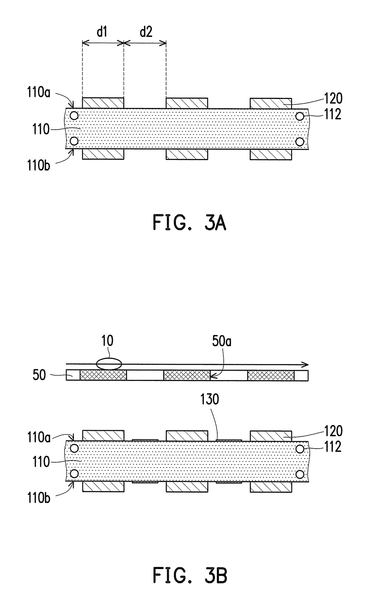
[0022]FIG. 1 is a schematic view of a structure of a circuit board according to an embodiment of the invention. In the embodiment, a circuit board 100 includes a circuit substrate 110, a first patterned circuit layer 120, a patterned glue layer 130, and a second patterned circuit layer 140. As shown in FIG. 1, in the embodiment, the first patterned circuit layer 120 may be formed on an upper surface 110a and a lower surface 110b of the circuit substrate 110 simultaneously. Additionally, the patterned glue layer 130 is disposed on a portion of the circuit substrate 110 exposed by the...


PUM


Abstract

A manufacturing method of a circuit board including the following steps is provided. A first patterned circuit layer is formed on a surface of a circuit substrate, and the first patterned circuit layer exposes a portion of the surface of the circuit substrate. A patterned glue layer is formed on the portion of the surface of the circuit substrate exposed by the first patterned circuit layer. A second patterned circuit layer is transfer-printed on the corresponding patterned glue layer. In addition, a structure of the circuit board is also mentioned.

Description

CROSS-REFERENCE TO RELATED APPLICATION[0001]This application claims the priority benefit of Taiwan application serial no. 105140170, filed on Dec. 6, 2016. The entirety of the above-mentioned patent application is hereby incorporated by reference herein and made a part of this specification.BACKGROUND OF THE INVENTIONField of the Invention[0002]The invention relates to a manufacturing method of a circuit board and a structure thereof, and particularly relates to a manufacturing method of a circuit board having a thick metal fine circuit structure and a structure thereof.Description of Related Art[0003]In a process of printing a circuit board, to manufacture fine line patterns of the circuit board, a modified semi-additive process (MSAP) is often used to manufacture a circuit layer having a line width of 40 microns (μm) or less on a circuit substrate. However, the aforementioned process requires high investment in equipments and materials, such that the material and production costs ...

Claims


Application Information

Patent Timeline
Patent Type & Authority Applications(United States)
IPC IPC(8): H05K3/20H05K3/38H05K1/11
CPCH05K3/20H05K2203/166H05K1/115H05K3/38H05K3/4644H05K2201/09727H05K2201/09918H05K2203/0522H05K2203/107H05K2203/1476
Inventor LIAO, PO-HSUANCHANG, CHI-MINYU, CHENG-PO
Owner UNIMICRON TECH CORP
Learn More