Eureka AIR delivers breakthrough ideas for toughest innovation challenges, trusted by R&D personnel around the world.

Method for producing a glass plate with a conductive printed wire and glass plate with a conductive printed wire

a technology of printed wire and glass plate, which is applied in the direction of conductive layers on insulating supports, instruments, electrographic processes, etc., can solve the problems of insufficient adhesion between the conductive printed wire and the inorganic substance after firing, the difference in thermal conductivity in a thickness direction, and the production of conductive printed wires. , to achieve the effect of good adhesion, good electrical performance and small roughness of the line width

Inactive Publication Date: 2009-04-16
ASAHI GLASS CO LTD
View PDF14 Cites 7 Cited by
  • Summary
  • Abstract
  • Description
  • Claims
  • Application Information

AI Technical Summary

Benefits of technology

[0014]According to the present invention, it is possible to form a conductive printed wire on a surface of a glass plate with good adhesion, the conductive printed wire being excellent in electrical performance and being small in roughness of the line width even when it is in the form of thick film. Accordingly, it is possible to form easily a conductive printed wire having desired heat generation performance or antenna performance on a surface of a glass plate.

Problems solved by technology

However, when a toner layer was formed in the form of thick film (having a line thickness of at least 20 μm) by these methods, there was a problem that difference in thermal conductivity in a thickness direction, produced at the time of firing is not negligible, so that adhesion between the conductive printed wire and the inorganic substance after firing might be insufficient.
In addition, there was a danger that cracks might result in the conductive printed wires by firing, and the electric performance (resistance) of the formed pattern deteriorated largely.
However, the larger the particle size of the conductive fine particles is, the larger the roughness of the line width of the conductive printed wire is, and accordingly, there was a problem that it was difficult to obtain a conductive printed wire of stable resistance.
Therefore, it was very difficult to produce a conductive printed wire in the form of thick film, which is usable sufficiently as a pattern of wire and which has a stable electric performance.

Method used


Image

  • Method for producing a glass plate with a conductive printed wire and glass plate with a conductive printed wire
  • Method for producing a glass plate with a conductive printed wire and glass plate with a conductive printed wire

Examples


Embodiment Construction

[0036]Now, an embodiment of the present invention will be described with reference to the drawings.

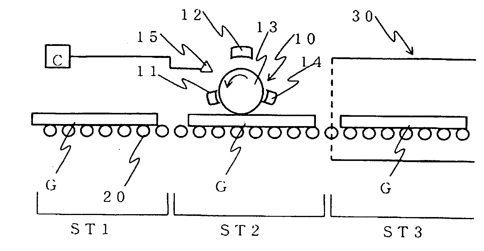
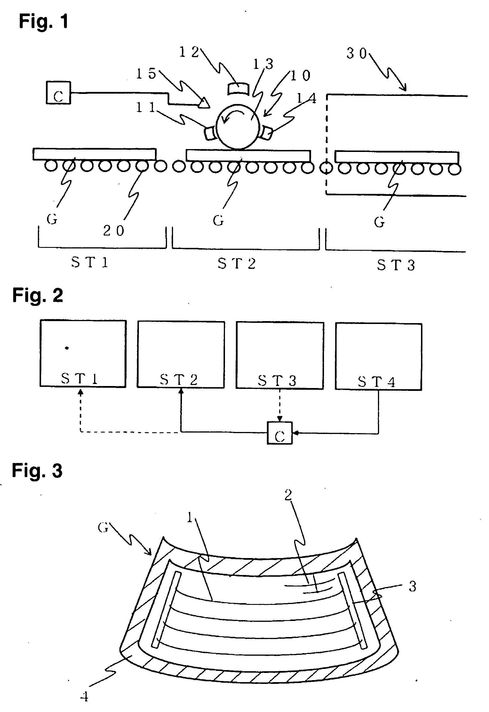
[0037]FIG. 1 is a schematic side view illustrating an example of a continuous process for producing a glass plate with a conductive printed wire of the present invention. The glass plate G is transported to a printing step via a step (ST1) of cutting into a predetermined shape, chamfering, cleaning, etc. In the printing step ST2, a toner containing conductive fine particles (hereinbelow, referred to as the conductive toner) is printed in a predetermined pattern on a surface of the glass plate G by an electro printing apparatus 10. The glass plate G having the toner printed in a prescribed pattern is transported to a firing step. In the firing step ST3, the glass plate G is heated to a predetermined temperature by a heating furnace 30, and the toner is fired to the surface of the glass plate G, whereby a glass plate having a conductive printed wire of predetermined pattern is prepared. ...


PUM

PropertyMeasurementUnit
number standard average particle sizeaaaaaaaaaa
thicknessaaaaaaaaaa

Abstract

Provided is a process for producing a glass plate with a conductive printed wire, which does not require a screen plate for each model, facilitates adjustments for desired heat generation performance or antenna performance, has an excellent adhesion to a glass plate surface, and minimizes surface roughness.The process for producing a glass plate with a conductive printed wire is characterized in that a laminate comprising a layer obtained by electro printing a first conductive toner having a number standard average particle size (D50) of 10 μm<D50≦50 μm and a layer obtained by electro printing a second conductive toner having a particle size (D50) of 5 μm≦D50≦10 μm is formed on a surface of a glass plate and the glass plate is heated to fire the toners to thereby form a conductive printed wire having a predetermined pattern on the surface of the glass plate.

Description

TECHNICAL FIELD[0001]The present invention relates to a process for producing a glass plate with a conductive printed wire and a glass plate with a conductive printed wire, particularly, it relates to a process for producing a conductive printed wire on a surface of a glass plate in the form of film (line thickness of at least 20 μm), the printed wire having excellent adhesion to the surface of a glass plate usable for a window of an automobile or the like.BACKGROUND ART[0002]A glass plate to be used for a window of an automobile, is provided with a conductive printed wire as a heater wire for defogging or as an antenna wire for receiving radio, television or the like. Such conductive printed wire is provided mainly on a rear window or on a rear side window of an automobile. The conductive printed wire consists mainly of a fired product of a paste containing silver. Specifically, a paste having silver, glass frit, a binder resin and so on is printed on a glass plate surface in a pre...

Claims


Application Information

Patent Timeline
Patent Type & Authority Applications(United States)
IPC IPC(8): G03G13/16H05K1/03
CPCC03C17/008C03C17/34G03G7/0093H01Q1/1278G03G9/0823G03G9/09708G03G9/0819B60J1/00G03G9/08H01B5/14
Inventor OKAHATA, NAOKIKASHIWABARA, SATOSHISUNAHARA, KAZUOOKADA, TOMOAKITAKEDA, KATSUHIKO
Owner ASAHI GLASS CO LTD
Why Eureka
Eureka Blog
Learn More