
Zinc Electrodes for Batteries

a zinc electrode and battery technology, applied in the field of porous zinc electrodes, can solve the problems of limited rechargeability, manufacturing cost, and limited application and achieve the effects of reducing the cost of manufacturing, reducing the use of zinc-air, and reducing the use of li-ion-based energy storag

Active Publication Date: 2018-05-10
THE UNITED STATES OF AMERICA AS REPRESENTED BY THE SECRETARY OF THE NAVY
View PDF0 Cites 17 Cited by
  • Summary
  • Abstract
  • Description
  • Claims
  • Application Information

AI Technical Summary

Benefits of technology

The electrochemical cell described in this patent has a unique anode (positive electrode) made by a method involving a sponge-like structure. The anode sponge is made by a process involving a mixture of powdered zinc and a liquid, followed by drying, annealing, and oxidation to form a shell of zinc oxide on the surface of the sponge. The use of this sponge anode results in an electrochemical cell with improved performance. A separator is used to separate the anode from the cathode (negative electrode), which can also improve performance. Overall, this patent describes a novel method for making a highly effective electrochemical cell with a unique anode.

Problems solved by technology

While Li-ion batteries have the benefits of low self-discharge, no memory effect, and above all, rechargeability, the broader application of Li-ion-based energy storage is limited by safety concerns, manufacturing costs, and lower specific energy densities (−1) relative to other promising battery technologies (Lee et al., “Metal-air batteries with high energy density: Li-air versus Zn-air”Adv.
While successful as a primary battery in certain commercial applications (e.g., the hearing-aid market), further utility of zinc-air is hindered by its limited rechargeability, lack of pulse power, and moderate utilization of theoretical discharge capacity (<60%).
These limitations are inherent to the electrochemical behavior of zinc (Zn) in the traditional anode form-factors that are used in commercial zinc-air batteries.
With increasing numbers of discharge-charge cycles, this shape change becomes more pronounced, eventually causing dendrites to grow from the negative electrode until they pierce the separator and cause electrical shorts that end battery operation.

Method used


Image

  • Zinc Electrodes for Batteries
  • Zinc Electrodes for Batteries
  • Zinc Electrodes for Batteries

Examples


example 1

Fabrication of Monolithic Zinc Sponges

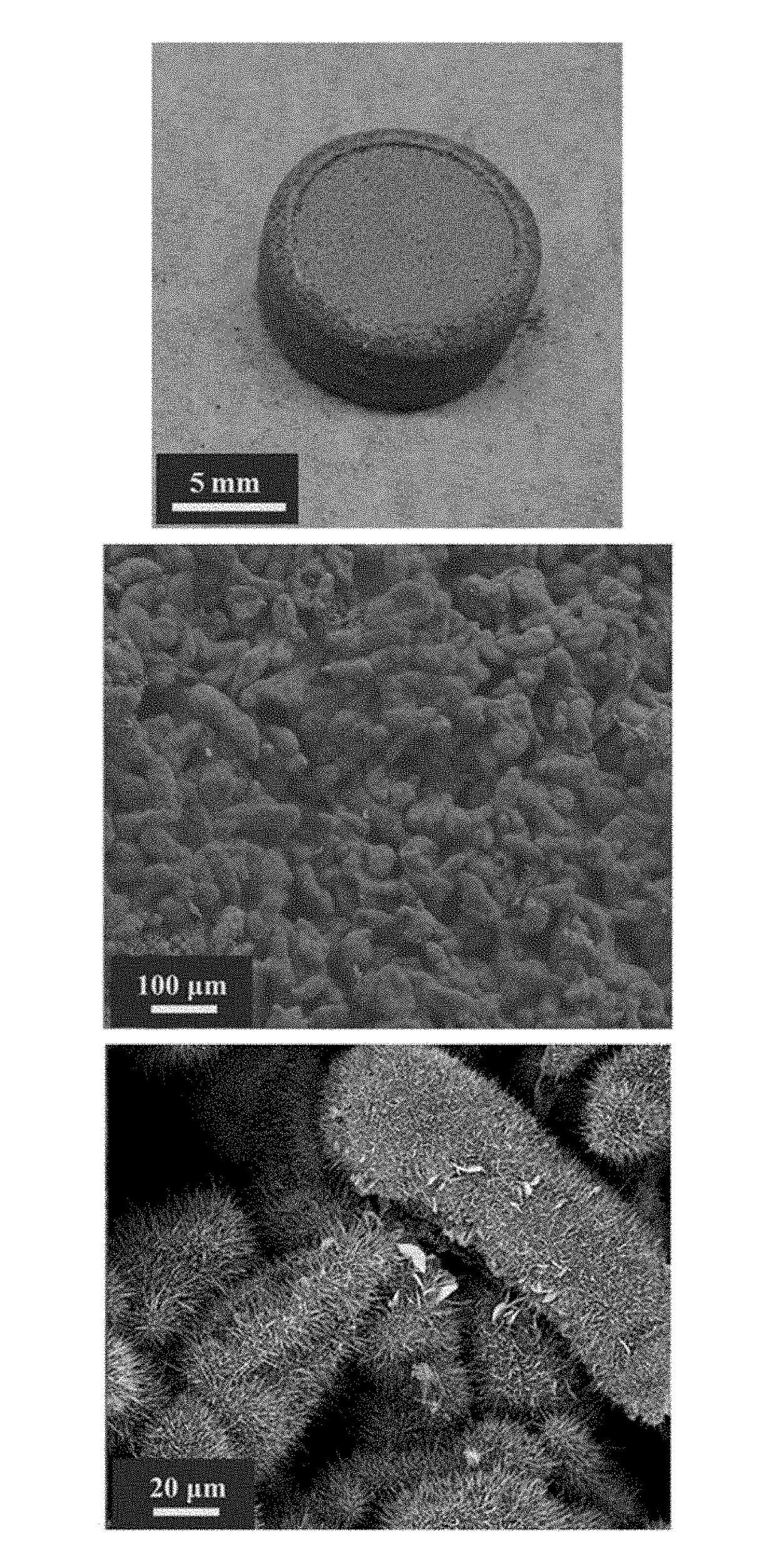
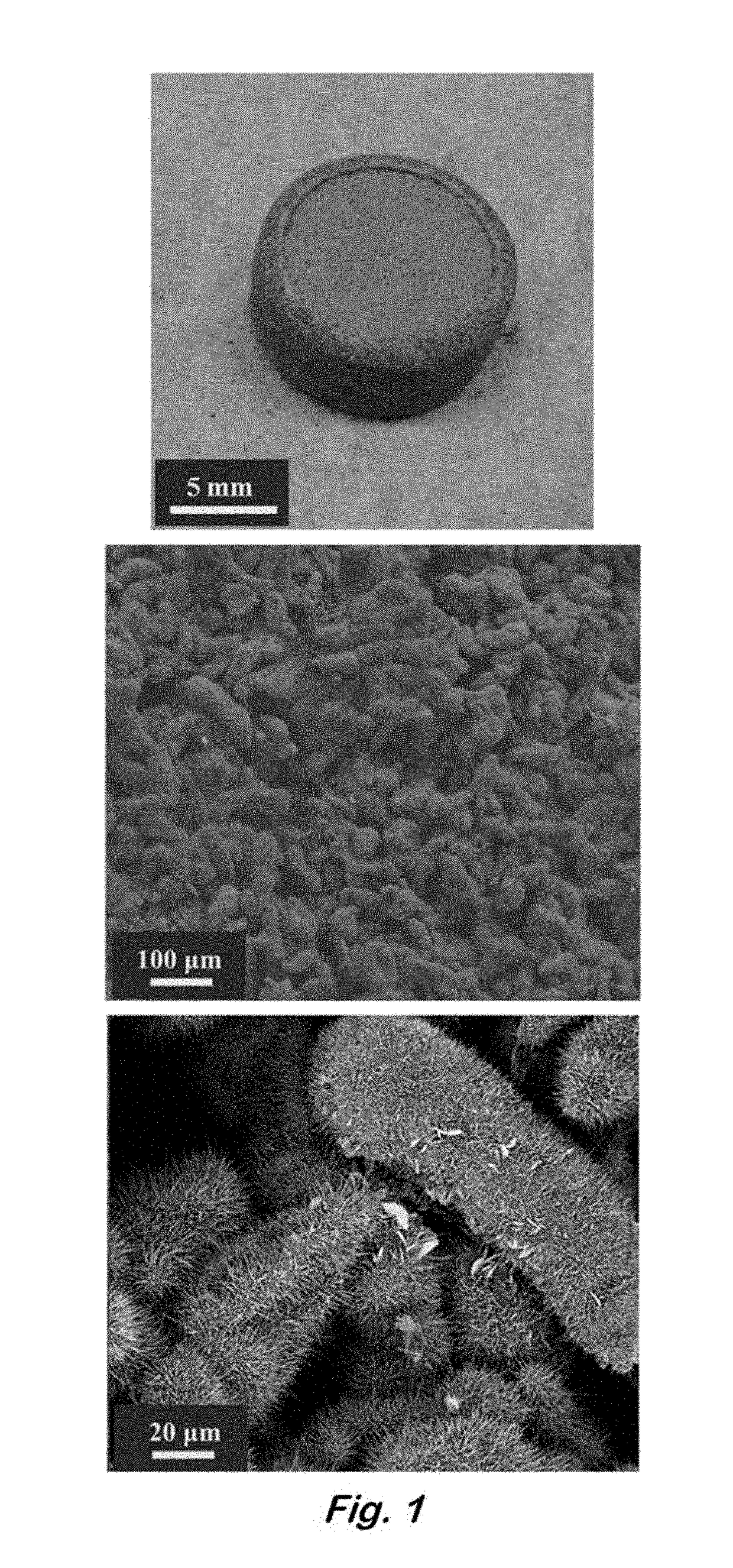
[0043]A typical preparation of zinc sponge electrodes begins with the formation of an emulsion of zinc powder in water and decane. In a small beaker or scintillation vial, 6.0 g of zinc powder that also contains 300-ppm indium and 285-ppm bismuth (as-received from Grillo-Werke AG) was added. The indium and bismuth additives are necessary to raise the overpotential for hydrogen evolution in alkaline electrolytes, while eliminating the need for toxic additives such as lead and mercury (Glaeser, U.S. Pat. No. 5,240,793). Water (1.027 mL) and decane (2.282 mL) were added along with an emulsifier, sodium dodecyl sulfate (6.3 mg) and emulsion stabilizer, carboxymethylcellulose (0.253 g). The use of these ingredients in the formation of zinc emulsions that are subsequently used to make zinc electrodes has been described previously (Drillet et al., “Development of a Novel Zinc / Air Fuel Cell with a Zn Foam Anode, a PVA / KOH Membrane, and a MnO2 / SiOC-based...

example 2

Zinc Sponges as a Negative Electrode in Zinc-Air Batteries

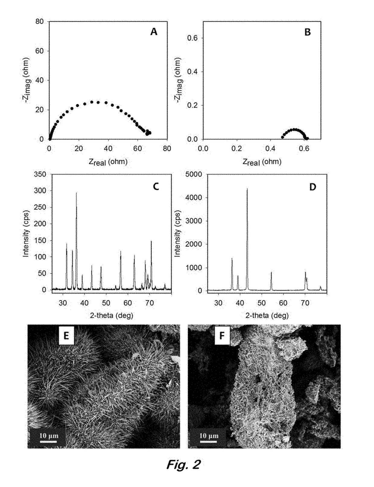
[0044]The intentional introduction of oxide to the zinc sponges enhances the mechanical integrity, allowing them to be routinely handled with decreased risk of fracture; however, a layer of oxide on the zinc lowers the initial capacity upon discharge and introduces contact resistance when assembling the zinc-containing cell (see Nyquist plots from electrochemical impedance spectroscopy (EIS) in FIG. 2A). In order to electrochemically reduce the ZnO coating, the sponge is used as part of the working electrode in a half-cell, three-electrode configuration with a Pt counter electrode and zinc quasi-reference electrode in 6 M KOH. A zinc sponge was placed in an envelope of tin-coated-copper mesh to form the working electrode. (Tin contacts were used because tin is galvanically compatible with zinc and corrosion of the electrode is suppressed that would otherwise be rampant with other current collectors (e.g., nickel, copper, etc....

example 3

Reversibility of Zinc Sponge Anodes

[0047]In order to study the reversibility of the 3D zinc sponge in a battery configuration, without the requirement of having an optimized cathode (e.g., bifunctionally catalytic for the ORR or OER), a symmetrical electrochemical cell containing an all-metal Zn sponge versus a Zn / ZnO sponge separated by an aqueous-compatible separator was used. The Zn / ZnO sponge was prepared by electroreducing some of the ZnO present from the post-heated sponge by applying −50 mV versus zinc for 10-min increments. The EIS and the OCP were measured after each cycle. The reduction of this sponge was terminated when the RCT in the EIS fell below 0.5 Ωcm−2, but the OCP remained greater than 30 mV vs. Zn, indicating high conductivity throughout the sponge network, yet ZnO remained. A second post-heated sponge was reduced at −50 mV versus Zn for 30-min increments as described in Example 2 until it was fully reduced to all metal Zn sponge with an OCP very close to 0 mV vs...


PUM

PropertyMeasurementUnit
temperatureaaaaaaaaaa
discharge current densitiesaaaaaaaaaa

Abstract

An article having a continuous network of zinc and a continuous network of void space interpenetrating the zinc network. The zinc network is a fused, monolithic structure. A method of: providing an emulsion having a zinc powder and a liquid phase; drying the emulsion to form a sponge; annealing and / or sintering the sponge to form an annealed and / or sintered sponge; heating the annealed and / or sintered sponge in an oxidizing atmosphere to form an oxidized sponge having zinc oxide on the surface of the oxidized sponge; and electrochemically reducing the zinc oxide to form a zinc metal sponge.

Description

[0001]This application is a continuation-in-part application of U.S. Pat. No. 9,802,254, issued on on Oct. 31, 2017. This application is also a continuation-in-part application of U.S. application Ser. No. 13 / 832,576, filed on Mar. 15, 2013, which claims the benefit of U.S. Provisional Application No. 61 / 730,946, filed on Nov. 28, 2012. These applications and all other publications and patent documents referred to throughout this nonprovisional application are incorporated herein by reference.TECHNICAL FIELD[0002]The present disclosure is generally related to porous zinc electrodes for use in batteries and other uses.DESCRIPTION OF RELATED ART[0003]The ongoing effort to fulfill the exigencies of ever-growing energy markets, including electric vehicles and portable electronic devices, has led to the investigation of battery technologies that promise to overcome some of the pitfalls of Li-ion batteries. While Li-ion batteries have the benefits of low self-discharge, no memory effect, ...

Claims


Application Information

Patent Timeline
Patent Type & Authority Applications(United States)
IPC IPC(8): H01M4/04H01M12/06H01M12/08H01M4/06H01M4/134H01M4/42H01M4/94
CPCH01M4/0471H01M12/06H01M12/08H01M4/06H01M4/134H01M4/42H01M4/94H01M2220/20H01M2220/30H01M2004/021H01M2004/027H01M4/38H01M10/054Y02E60/10
Inventor PARKER, JOSEPH F.ROLISON, DEBRA R.LONG, JEFFREY W.KO, JESSE S.
Owner THE UNITED STATES OF AMERICA AS REPRESENTED BY THE SECRETARY OF THE NAVY
Learn More