
Radiotherapy dose distribution measurement

a radiation therapy and dose technology, applied in the direction of x/gamma/cosmic radiation measurement, instruments, therapy, etc., can solve the problems of inability to perform on a living patient, inherently inaccurate measurements, and difficult to carry out, so as to achieve convenient movement and alignment, easy to see, and constant thickness

Active Publication Date: 2018-05-03
ELEKTA AB
View PDF0 Cites 8 Cited by
  • Summary
  • Abstract
  • Description
  • Claims
  • Application Information

AI Technical Summary

Benefits of technology

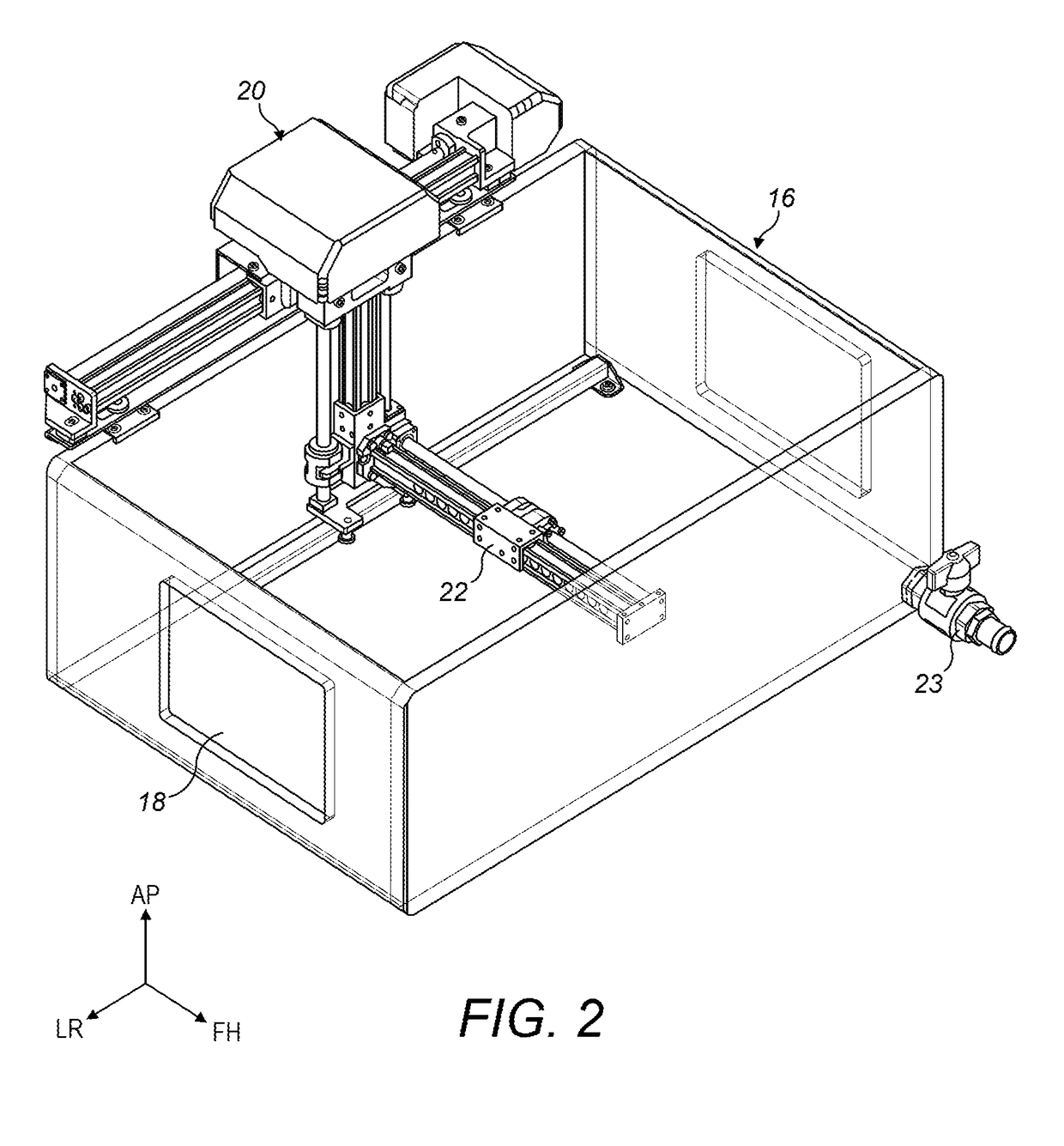
The present invention provides a method for improving the accuracy and precision of dose measurements and radiation beam characterization in MRLs or PET apparatuses. This is achieved by taking dose measurements in both the vertical and horizontal directions, using a tank that is shorter and wider than conventional tanks, and using a detector holder with a reference point and a radio-opaque marker. The tank may also have a window to reduce attenuation of the beam. The invention also includes a tank with a thinner wall to allow for quicker filling and emptying, and a tank with optically transparent walls to allow for easy visual inspection.

Problems solved by technology

This cannot be performed on a living patient because it would risk applying an excessive dose of radiation, and it would be difficult to carry out in solid tissue, so it is usually carried out by submerging a waterproof detector in a tank full of distilled water.
In these known processes the final measurements are inherently inaccurate: firstly, the placement of the tank is performed by aligning by eye with laser pointers; secondly, the depth of the water is determined by visual inspection of an ODI reading from a piece of paper floating on the water surface (visual inspection is inherently inaccurate, and takes no account of surface tension and wetting effects on the paper), and thirdly, these visual alignments are merely surrogates for the position of the radiation beam, which is what needs to be measured.
There are additional problems where the radiotherapy apparatus is an MRL, having a cylindrical or near-cylindrical bore in which the patient is positioned for therapy (usually the bore is not much bigger than it needs to be to accept an averagely-sized patient, who may have temporary frames or other fittings attached so as to be able accurately to place a particular anatomical part or region within the bore), or any apparatus where space is tight and visibility difficult.
Because the MRL radiotherapy beam isocentre is in the middle of a bore of about 1-2 m in length and no more than about 1-1.5 m in diameter, the physical space for a water tank is very limited, and the conventional tanks used in a linac are unsuitably large (usually these tanks are rectangular, like a large fish tank, with walls of radiation-transparent material of constant thickness, and with their height being equal to or greater than the maximum front-to-rear measurement of a typical patient and their width being equal to or greater than the maximum side-to-side measurement of a typical patient); because the moving mechanism is mounted to the outside of the tank, this means that the maximum size of the tank is limited, and so is the range through which the mechanism can move the detector, to the extent that dose distribution measurements cannot be taken at every position within the bore.
It is not possible to use lasers for aligning the tank or an ODI for measuring the surface of the water because there is no line-of-sight available, this being blocked by the magnet coils surrounding the bore.

Method used


Image

  • Radiotherapy dose distribution measurement
  • Radiotherapy dose distribution measurement
  • Radiotherapy dose distribution measurement

Examples


Embodiment Construction

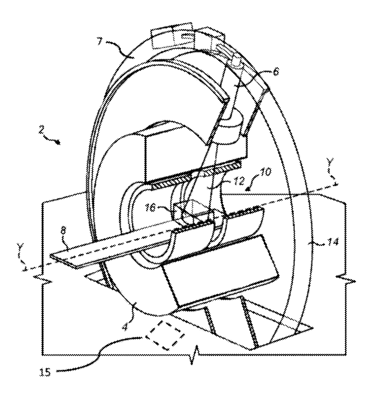
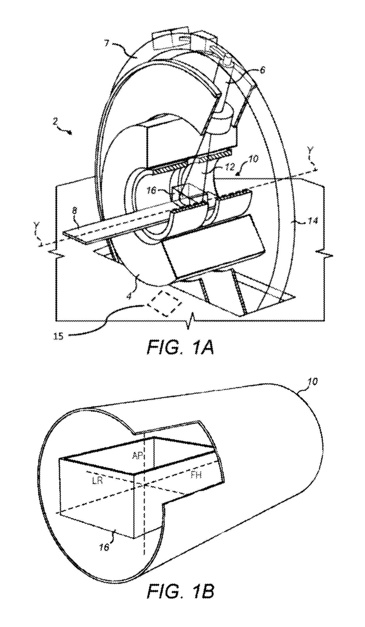
[0026]FIG. 1 shows a system 2 comprising a radiotherapy apparatus 6 and a magnetic resonance imaging (MRI) apparatus 4. The system includes a couch 8, for supporting a patient in the bore 10 of the system. The couch 10 is movable along a horizontal, translation axis (labelled “Y”), such that a patient resting on the couch may be moved into the bore 10 of the MRI apparatus 4 and into the path of the beam of radiotherapeutic radiation 12 emitted by the radiotherapy apparatus 6. The MRI apparatus 4 is for producing near real-time imaging of a patient positioned on the couch 10. The radiotherapy apparatus 6 is mounted to gantry 7 which in use rotates around the bore 10 along a circular path 14 so as to irradiate a patient from different angles and an EPID 15 (shown in phantom) is mounted on the other side of the gantry 7 to rotate diametrically opposite the radiotherapy apparatus 6 to acquire images once the beam 12 has passed through a patient (or anything else inside the bore and in t...


PUM


Abstract

A method for measurement of dose distribution in a radiotherapy apparatus includes providing a detector holder situated at least partially within a tank, the detector holder comprising a radio-opaque marker and a visual reference point, the marker and the reference point being separated and in a fixed spatial relationship to each other; locating the tank within a bore of the radiotherapy apparatus; rotating a gantry and monitoring the position of the detector holder with an imaging apparatus; vertically displacing the detector holder until the reference point is positioned at a desired level, and adding liquid to or removing liquid from the tank until the surface of the liquid is level with the reference point. Features of the detector holder and tank are also described.

Description

CROSS-REFERENCE TO RELATED PATENT APPLICATIONS[0001]This application claims the benefit and priority of prior United Kingdom Patent Application No. 1618326.1, filed on Oct. 31, 2016, the entire contents of which are incorporated by reference herein.BACKGROUNDField of the Invention[0002]The present invention relates to techniques for the measurement of radiotherapeutic dose distribution in radiation therapy apparatus, particularly but not exclusively in Magnetic Resonance (MR)-guided linear accelerator apparatus.Background Art[0003]Radiotherapeutic apparatus is well-known, in which a source of radiation emits a beam of radiation that is directed toward a patient in order to destroy or otherwise harm cancerous cells within the patient. It is normal to collimate the beam so as to limit its spatial extent to a desired region within the patient (usually the tumour containing the cancerous cells or a sub-section of the tumour) and to avoid irradiating nearby healthy and / or sensitive tissu...

Claims


Application Information

Patent Timeline
Patent Type & Authority Applications(United States)
IPC IPC(8): A61N5/10
CPCA61N5/1075A61N5/1081A61N2005/1076A61N5/1039A61N5/1071G01T1/02G01T1/29A61N2005/1055A61N2005/1054
Inventor PENCEA, CORNELIU STEFANHARASIMOWICZ, JANUSMARINOS, NIKOLASBYRNE, JULIAN PETER DAVID
Owner ELEKTA AB
Learn More