Adaptive low-dropout regulator having wide voltage endurance range, chip and terminal
- Summary
- Abstract
- Description
- Claims
- Application Information
AI Technical Summary
Benefits of technology
Problems solved by technology
Method used
Image
Examples
embodiment 1
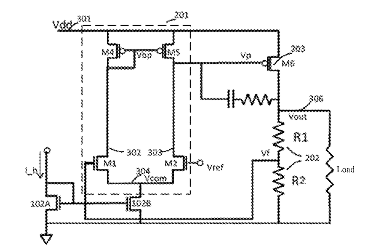
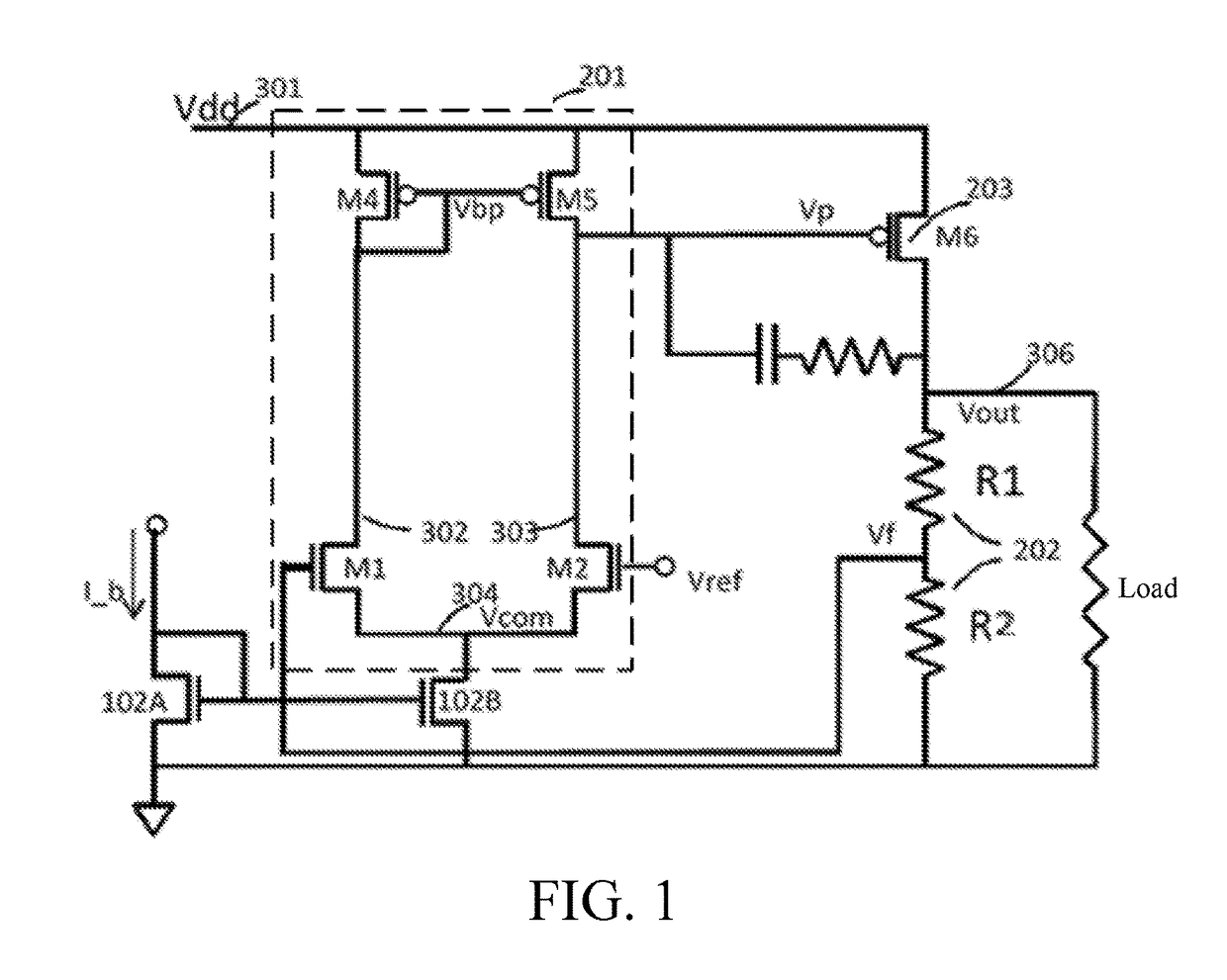
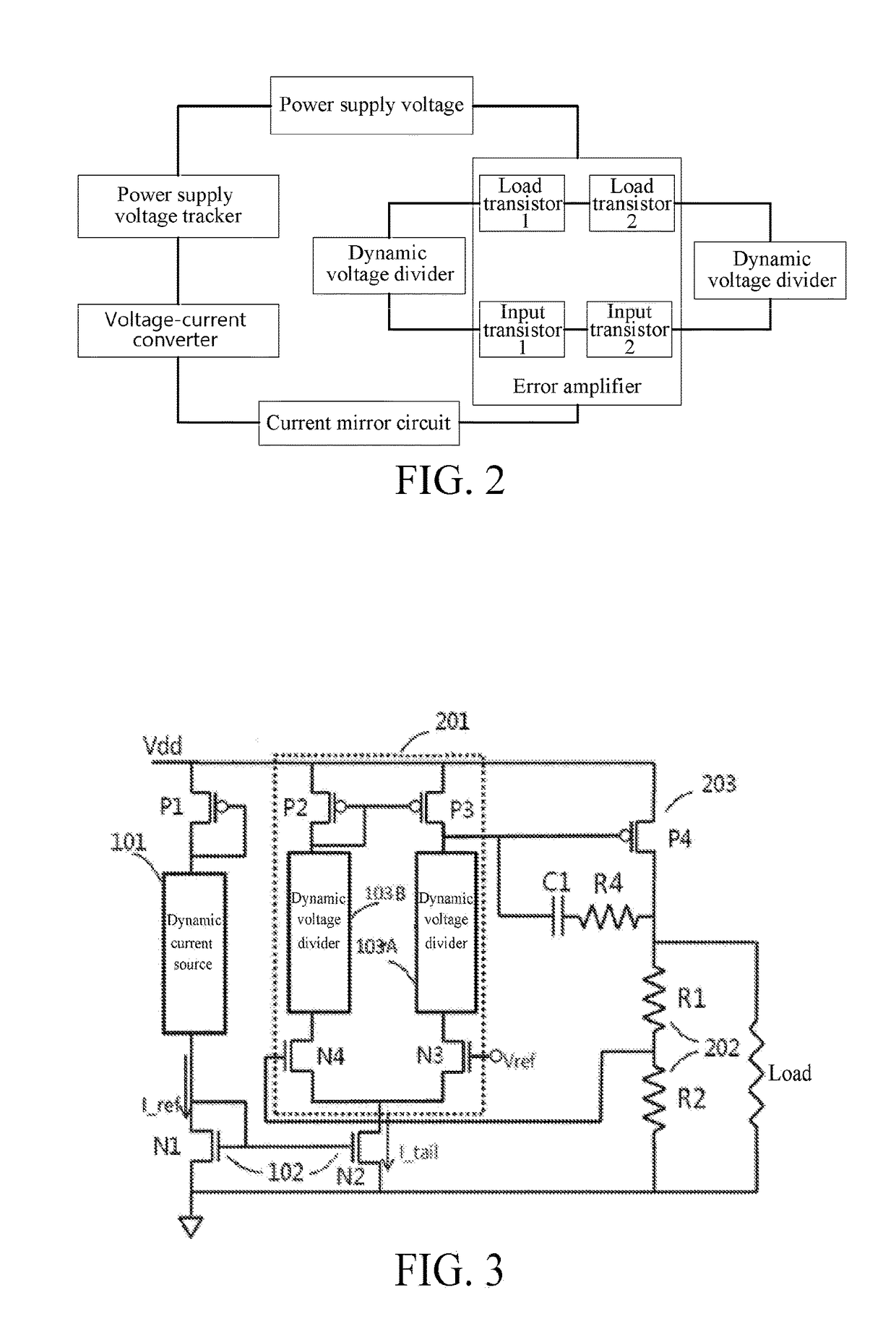
[0036]Referring to FIG. 3, an adaptive dynamical adjustment circuit includes a power supply voltage tracker, a dynamic current source 101, a current mirror circuit 102, and dynamic voltage dividers 103 (103A / 103B). The power supply voltage tracker is implemented as a PMOS transistor P1, a source of the PMOS transistor P1 is connected to a power supply voltage, and a drain thereof is connected to a gate and the dynamic current source 101. In this embodiment, a voltage-current converter is the dynamic current source 101, and is configured to convert a change of the power supply voltage into a change of a current, and is located on a path on which a reference current is generated. In this embodiment, a simplest circuit structure is used for a current of the current mirror circuit 102. The circuit structure includes two NMOS transistors N1 and N2 whose gates are connected to each other. The gate of N1 is connected to a drain of N1, the drain is connected to the dynamic current source 10...
embodiment 2
[0038]Referring to FIG. 5, this embodiment is further detailed based on Embodiment 1. A dynamic current source and dynamic voltage dividers are implemented as resistors. In FIG. 5, the dynamic current source is Rb, the dynamic voltage dividers are Rd1 and Rd2. How to select a proper element parameter to enable a linear regulator to have a wider voltage endurance range is described below with reference to the accompanying drawings and specific calculation processes.
[0039]The dynamic current source in this embodiment is Rb, and a current passing through Rb may be calculated by using the following formula:
I_ref=(Vdd−|Vtp|−Vtn) / Rb (3)
[0040]A reference voltage I_ref changes with a power supply voltage Vdd, and is transmitted to an error amplifier by way of a current mirror circuit, to serve as a bias current I_tail of the error amplifier. Assuming that a mirror multiple of the current mirror circuit is N, that is, N2 is N times N1, I_tail=N*I_ref.
[0041]In this embodiment, the dynamic vo...
PUM
 Abstract
Description
Claims
Application Information
 - R&D
- Intellectual Property
- Life Sciences
- Materials
- Tech Scout
- Unparalleled Data Quality
- Higher Quality Content
- 60% Fewer Hallucinations
Browse by: Latest US Patents, China's latest patents, Technical Efficacy Thesaurus, Application Domain, Technology Topic, Popular Technical Reports.
© 2025 PatSnap. All rights reserved.Legal|Privacy policy|Modern Slavery Act Transparency Statement|Sitemap|About US| Contact US: help@patsnap.com


