
Measurement method, measurement device, and program

a measurement device and measurement method technology, applied in the direction of liquid/fluent solid measurement, instruments, packaged goods types, etc., can solve the problems of high accuracy, high speed, and inability to measure the volume of aqueous drug solution with high precision and high speed, and achieve the effect of reducing the calculation process, detecting the distance at each position more accurately, and high accuracy

Active Publication Date: 2018-03-08
FUJIFILM CORP
View PDF2 Cites 7 Cited by
  • Summary
  • Abstract
  • Description
  • Claims
  • Application Information

AI Technical Summary

Benefits of technology

The patent describes a method to accurately measure the volume of a drug solution in each needle-like recess of a mold. This is accomplished through a non-destructive and high-speed measurement process, which can be carried out regardless of the type of drug. The measurement accuracy is around 0.1%, making it suitable for mass production. This method provides valuable information during the development of drug administration devices, allowing for optimized design and production.

Problems solved by technology

However, even in a case where the high-precision electronic balance is used, it is difficult to measure the volume of the aqueous drug solution with high precision and high speed.
The reasons for this are as follows: 1) since a measurement result of the electronic balance in a case where a very small amount is measured is greatly affected by a measurement environment (temperature, humidity, and convection) and a mold material (for example, water absorption characteristics, and it is easy for static electricity to be generated), the measurement result becomes unstable.
However, a measured value (a weight value) is not stable when an empty mold before filling is weighed even when a balance has a resolution of 0.01 mg due to an influence of a measurement environment (temperature, humidity, and convection) and characteristics of a mold material (silicon rubber itself has water absorption characteristics and it is easy for static electricity to be accumulated).
Therefore, it is difficult to acquire measurement results with high accuracy (for example, 1% or less) even when the high-precision electronic balance is used.
2) Further, there is a problem in that a measurement time of an electronic balance including the high-precision electronic balance is long.
For example, in a case where tens of MNAs (also called mold patches) are formed on one sheet, it is necessary to separate each MNA (mold patch) from the sheet in order to perform the measurement, but this work is not allowed in an actual production process.
That is, a weight measurement method using a high-precision electronic balance is not suitable for a roll-to-roll production method.
Further, in the measurement using the high-precision electronic balance as described above, the volume of the aqueous drug solution of each needle-like recess of the mold cannot be individually measured.
As a result, a variation in the volume of the aqueous drug solution of each needle-like recess cannot be measured.
Accordingly, the method can be carried out irrespective of a kind of drug, but the method is a destructive inspection (reason: each micro-needle of MNA is colored with blue), and speed and accuracy are low (reason: the blue micro-needle peeled from the mold is observed with a video microscope).
Thus, the method is not suitable for nondestructive, high-precision, and high-speed inspection which is required for mass production.
This method is not suitable for inspection required for mass production due to the same reason as described above (the method is a destructive inspection, a measurement time is one to two days, and measurement accuracy is lower than in the gravimetric measurement with a high-precision balance).

Method used


Image

  • Measurement method, measurement device, and program
  • Measurement method, measurement device, and program
  • Measurement method, measurement device, and program

Examples


second embodiment

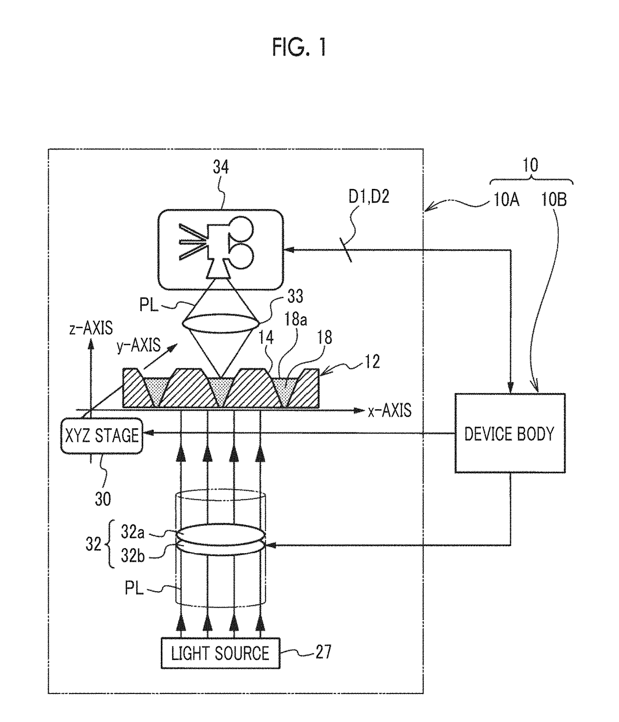
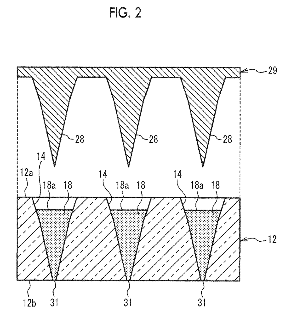
[0251]FIGS. 22A and 22B are illustrative diagrams illustrating a process of detecting the distance H using the measurement device 10 of a second embodiment. In the first embodiment (including the modification example thereof, hereinafter the same), as illustrated in FIGS. 11B and 11C, the distance detection unit 59 detects the distance H at each position in the drug surface 18a using [General Formula 5] on the assumption that the incident light intensities (incidence intensities) of the measurement light PL in the wavelength range λ1 and the measurement light PL in the wavelength range λ2 incident on the second surface 12b are both “I0”. On the other hand, the distance detection unit 59 of the second embodiment detects the distance H at each position in the drug surface 18a on the assumption that the incident light intensities (incidence intensities) of the measurement light PL in the wavelength range λ1 and the measurement light PL in the wavelength range λ2 incident on the second ...

third embodiment

[0264]FIGS. 23A and 23B are illustrative diagrams illustrating a process of detecting the distance H in the measurement device 10 of the third embodiment. In each of the above embodiments, [General Formula 5] and [General Formula 13] are derived from a formula in which the transmitted light intensity of the measurement light PL in the wavelength range λ2 is divided by the transmitted light intensity of the measurement light PL in the wavelength range λ1 as shown in [General Formula 4] and [General Formula 12] to obtain the distance H. On the other hand, in the third embodiment, the distance H is obtained from a difference between the transmitted light intensity of the measurement light PL in the wavelength range λ1 and the transmitted light intensity of the measurement light PL in the wavelength range λ2 in consideration of an influence of stray light indicated by a sign “φ” (a suffix is omitted), as illustrated in FIGS. 23A and 23B. Here, the stray light is light different from the...

fourth embodiment

[0281]FIGS. 24A, 24B, and 24C are illustrative diagrams illustrating a process of detecting the distance H in the measurement device 10 of the fourth embodiment. In each of the above embodiments, the distance H at each position of the drug surface 18a in the needle-like recess 14 is detected using the measurement light PL in the two wavelength ranges λ1 and λ2, whereas in the fourth embodiment, the distance H at each position of the drug surface 18a in the needle-like recess 14 is detected using the measurement light PL in three wavelength ranges λ1, λ2, and λ3. Here, the measurement light PL in the wavelength range λ3 corresponds to a third measurement wave of the present invention. For example, in this embodiment, the wavelength range λ1 is 1350 nm, the wavelength range λ2 is 1450 nm, and the wavelength range λ3 is 1550 nm.

[0282]The measurement device 10 of the fourth embodiment has basically the same configuration of the measurement device 10 of each of the above embodiments exce...


PUM

PropertyMeasurementUnit
weightaaaaaaaaaa
weightaaaaaaaaaa
wavelengthaaaaaaaaaa

Abstract

The present invention provides a measurement method, a measurement device, and a program capable of non-destructively measuring a volume of an aqueous solution of a drug in each needle-like recess of a mold with high accuracy. A measurement method according to a preferred embodiment of the present invention includes a measurement wave intensity acquisition step of acquiring, for each needle-like recess, an intensity of a measurement wave transmitted through a drug in a needle-like recess, absorbed by the drug by an amount according to a distance by which the measurement wave is transmitted through the drug, and emitted from the drug; and a volume acquisition step of acquiring a volume for each needle-like recess on the basis of the intensity of the measurement wave for each needle-like recess acquired in the measurement wave intensity acquisition step.

Description

CROSS-REFERENCE TO RELATED APPLICATIONS[0001]This application is a Continuation of PCT International Application No. PCT / JP2016 / 055379 filed on Feb. 24, 2016, which claims priorities under 35 U.S.C. § 119(a) to Japanese Patent Application No. 2015-047619 filed on Mar. 10, 2015 and Japanese Patent Application No. 2016-009968 filed on Jan. 21, 2016. Each of the above applications is hereby expressly incorporated by reference, in their entirety, into the present application.BACKGROUND OF THE INVENTION1. Field of the Invention[0002]The present invention relates to a measurement method, a measurement device, and a program for measuring a volume (amount of filling) of a drug filled in a needle-like recess of a mold for forming a micro-needle.2. Description of the Related Art[0003]In recent years, a micro-needle array (hereinafter abbreviated as MNA) is known as a novel dosage form capable of administering a drug such as insulin, vaccines, and human Growth Hormone (hGH) into the skin witho...

Claims


Application Information

Patent Timeline
Patent Type & Authority Applications(United States)
IPC IPC(8): G01B11/24G01B11/22G01F17/00G01F22/00
CPCG01B11/2441G01B11/22G01F17/00G01F22/00A61M5/31A61M5/1782B65B3/006G01F25/0084G01B11/00G01B11/24A61M2037/0053G01F23/292
Inventor HU, YIMUROOKA, TAKASHI
Owner FUJIFILM CORP
Learn More