High voltage DC power supply for high power radio frequency amplifiers
a high-voltage dc power supply and amplifier technology, applied in the direction of electric variable regulation, process and machine control, instruments, etc., can solve the problems of reducing the control bandwidth, generating substantial line harmonics, and significant deterioration of the input power factor,
- Summary
- Abstract
- Description
- Claims
- Application Information
AI Technical Summary
Benefits of technology
Problems solved by technology
Method used
Image
Examples
example 1
em Reliability with Active Redundancy
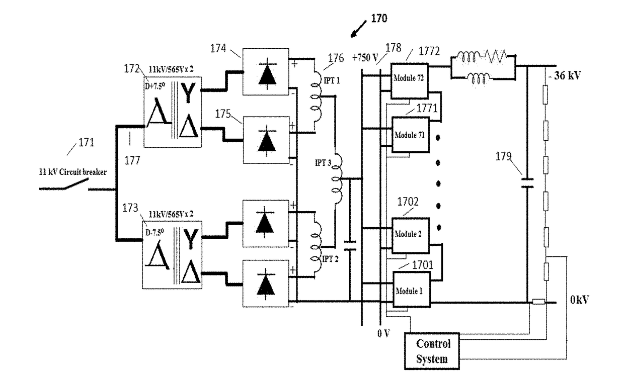
[0094]Eight out of seventy two numbers of power modules are intentionally kept as active redundant in the power supply so that failure of up to eight power modules will not affect the operation of RF amplifier.
[0095]The probability of failure of “i” units out of total “N” units is given as
P(i)=NCi(1−p)ipN-i
[0096]Where p=reliability of individual unit
NCi=N! / (i!×(N−i)!)
[0097]Taking reliability of individual power modules to be 95%, the probability of failure of up to eight power modules are estimated as under.
[0098](a) The probability that all 72 power modules will work well is given by
P(0)72C0(1−p)0p72=0.0249
[0099](b) The probability of failure of one power module out of 72 is given by
P(1)=72C1(1−p)1p71=0.0943
[0100](c) The probability of failure of two power modules out of 72 is given by
P(2)=72C2(1−p)2p70=0.1762
[0101](d) The probability of failure of three power modules out of 72 is given by
P(3)=72C3(1−p)3p69=0.2164
[0102](e) The probability of fa...
example 2
ibility for Higher Output Voltage
[0109]The present supply scheme has wide flexibility in increasing the output voltage to higher value by adding number of DC-DC power modules 130 in series, without requiring any modifications in the existing power modules. High voltage isolation may be provided in the transformers 138 of DC-DC power modules to be floated at higher voltage. Input section also needs no modification as long as total power drawn is within its full power rating. This is a unique feature of the present supply scheme as no other prior art scheme provide flexibilities in increasing the output voltage, as common isolation between input and output is provided by its main transformer.
example 3
ith IOT Amplifier
[0110]The present power supply is tested at −36 kV, 4.5 Amp on an E2V make, IOTD2130 Inductive Output Tube (TOT) RF amplifier and the experimental results obtained are presented. The input system always remains 24 pulsed for the entire range of the operation of this power supply. FIG. 6 shows a 24-pulse input line current waveform in L2 phase and FIG. 7 shows its frequency spectrum with predominant 23rd and 25th harmonics 71 and 72, which are near to the expected ideal waveform. All IGBTs 134 to 137 in the inverter bridge of power modules are operated in zero voltage switching modes over the entire operating range. It is observed that the DC-DC module output has voltage overshoots, which affect the output performance and was reduced by putting a small capacitor across the rectified output. A diode is placed in series with the capacitor for not allowing its stored energy to be dumped into the RF amplifier under any arcing conditions. Experimental voltage 211 and curr...
PUM
 Abstract
Description
Claims
Application Information
 - R&D
- Intellectual Property
- Life Sciences
- Materials
- Tech Scout
- Unparalleled Data Quality
- Higher Quality Content
- 60% Fewer Hallucinations
Browse by: Latest US Patents, China's latest patents, Technical Efficacy Thesaurus, Application Domain, Technology Topic, Popular Technical Reports.
© 2025 PatSnap. All rights reserved.Legal|Privacy policy|Modern Slavery Act Transparency Statement|Sitemap|About US| Contact US: help@patsnap.com


