Eureka AIR delivers breakthrough ideas for toughest innovation challenges, trusted by R&D personnel around the world.

Electric actuator with pre-heating

a technology of electric actuators and actuators, applied in the direction of safety/protection circuits, hybrid vehicles, pulse techniques, etc., can solve the problems of life-threatening situations, large contactors, and relatively expensive electromechanical switches, and achieve rapid preheating of coils, reduce coil excitation, and reduce coil power loss

Inactive Publication Date: 2017-10-19
ROBERT BOSCH GMBH
View PDF4 Cites 7 Cited by
  • Summary
  • Abstract
  • Description
  • Claims
  • Application Information

AI Technical Summary

Benefits of technology

The patent describes a solution for controlling the temperature of coils in electromechanical switches used in battery disconnector units. By using a combination of pulse-width modulation and direct-current preheating, the solution can rapidly increase the coil temperature without causing the switch to close, reducing power loss and limiting the temperature to safe levels. This approach can improve the design of the output stage and reduce costs. The technical effects of this solution include improved efficiency, reduced power loss, and lower temperatures.

Problems solved by technology

In healthy adults, a life-threatening situation is considered to exist starting at a touch voltage of 50 volts of alternating current or 120 volts of direct current.
In most cases, the main contactors are very powerful, large, and relatively expensive electromechanical switches.
In this case, a very high switch-on current could flow, which a typical electronic driver stage would in no way be capable of delivering.
Such a switch-on current could result in the destruction of the electronic output stages.
The driver stages would need to be designed with greater complexity merely for the low-temperature condition, which results in considerably higher costs, however.

Method used


Image

  • Electric actuator with pre-heating
  • Electric actuator with pre-heating
  • Electric actuator with pre-heating

Examples


Embodiment Construction

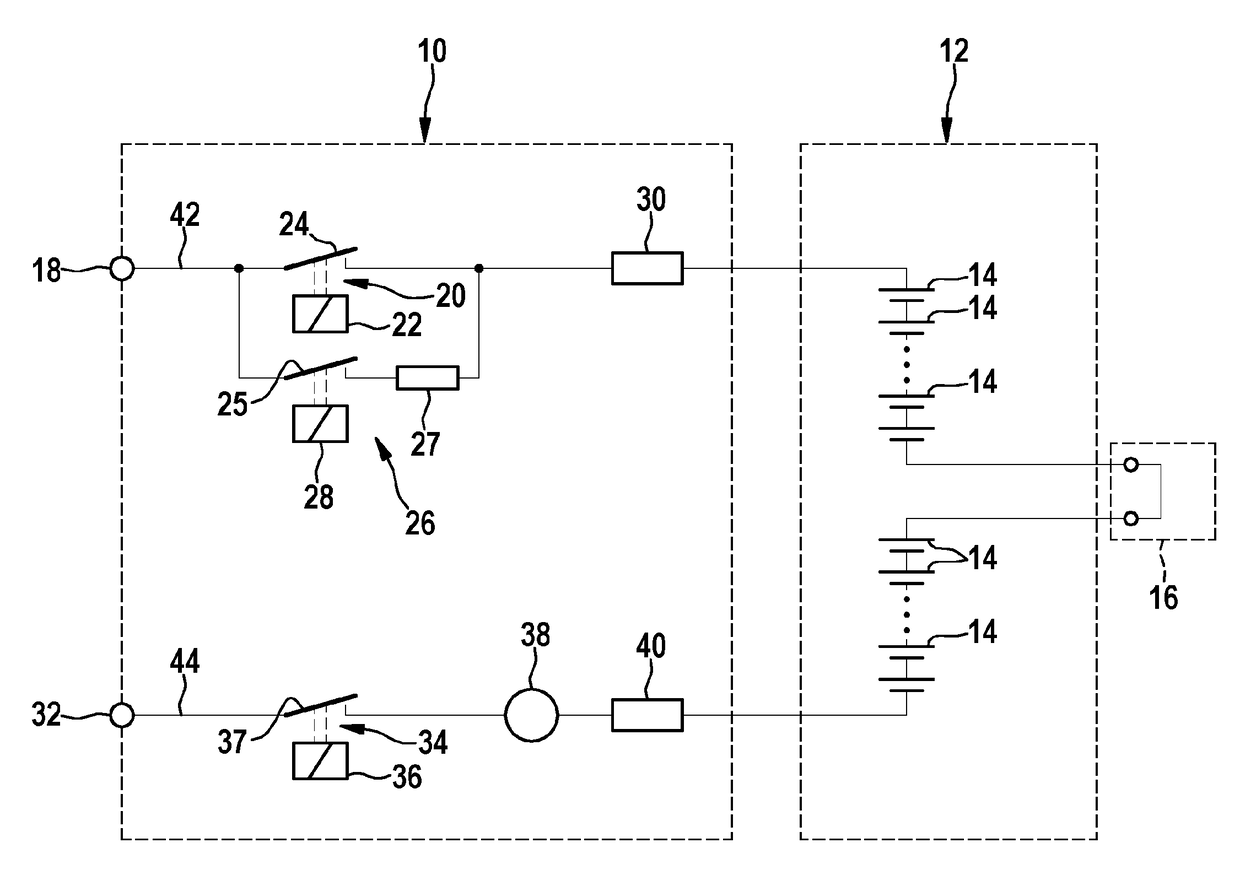
[0028]The representation according to FIG. 1 shows a simplified diagram of an electrical energy accumulator comprising a battery disconnector unit.

[0029]The battery disconnector unit 10 represented in FIG. 1 is connected to a high voltage battery 12. Said high voltage battery includes a battery pack or a battery module, within which a number of battery cells 14 is electrically interconnected. The high voltage battery 12 according to the representation in FIG. 1 further includes a service plug 16.

[0030]The battery disconnector unit 10, which is labeled with reference number 10, includes a battery positive pole 18 and a battery negative pole 32. The battery disconnector unit 10 contains, in a first battery connecting lead 42, a main contactor 20 for the battery positive pole 18. The main contactor 20 includes an electromechanical switch 24 which is referred to as a main contactor switch for the battery positive pole 18 and is actuated via a main contactor coil 22. A precharging contac...


PUM


Abstract

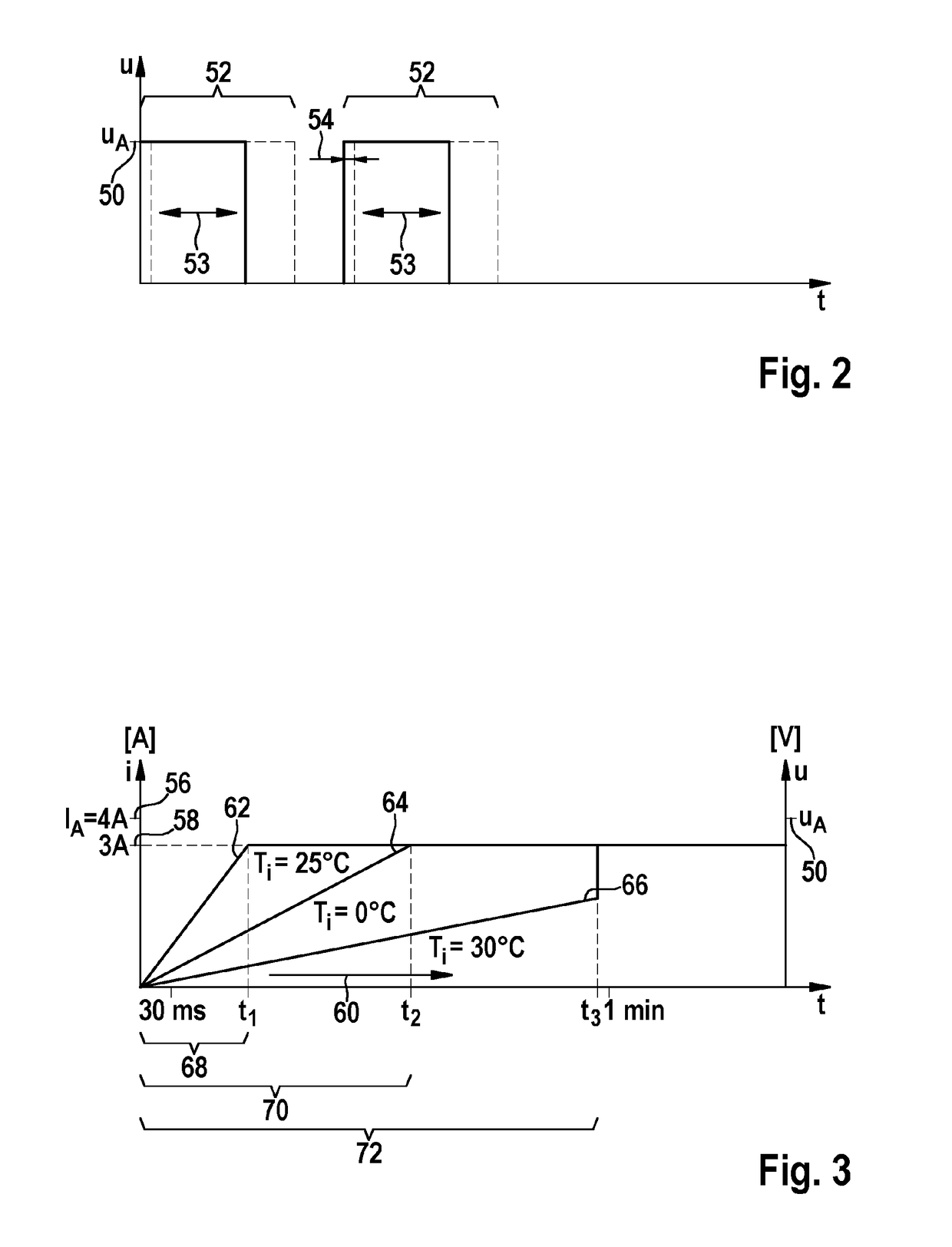
The invention relates to a method for operating an electrical network, in particular an onboard network of a vehicle, in particular of a hybrid vehicle (HEV), of a plug-in hybrid vehicle (PHEV) or of an electric vehicle (EV). Said network comprises a battery system, which contains a battery separation unit (10), with which a high-voltage battery (12) can be separated from a battery positive pole (18) and / or a battery negative pole (32) or from both battery poles (18, 32) of the on-board network. A main contactor and / or precharging contactor coil (22, 28, 36) of at least one electromagnetic switch (20, 24) is pre-heated. In the case of a pulse-width modulation signal control, the actuation takes place with a fraction (54), preferably 10% to 30%, of an activation pulse width. In the case of actuation by direct current signals, the main contactor and / or precharging contactor coils (22, 28, 36) are preheated according to the temperature in the interior of the electrical energy accumulator with heating gradients (62, 64, 66) chosen according to the temperature.

Description

BACKGROUND OF THE INVENTION[0001]The invention relates to a method for operating an electrical network, in particular an on-board electrical network of a vehicle, such as, for example, of a hybrid vehicle or of an electric vehicle comprising a battery system which includes a battery disconnector unit. By means of this battery disconnector unit, an electrical energy accumulator can be disconnected from the on-board electrical network at a battery positive pole and / or at a battery negative pole.[0002]Lithium ion battery systems are currently used most of the time in stationary applications such as, e.g., wind power stations, and in units used for emergency power supply, such as in mobile applications, such as, for example, in hybrid-electric vehicles (HEV) or electric vehicles (EV). Very high requirements are placed on such battery systems in respect of the usable energy content, the usable power, the level of charging-discharging efficiency, a non-presence of a memory effect, and on ...

Claims


Application Information

Patent Timeline
Patent Type & Authority Applications(United States)
IPC IPC(8): H02J7/00B60L3/00H03K3/017B60L11/18
CPCH02J7/0031B60L11/1875B60L3/0046Y10S903/903H03K3/017B60L2240/36H02J7/0045B60L3/0084B60L58/10B60L2240/662H01H47/325B60L58/27H01H50/12Y02T10/70Y02T10/72Y02T90/14Y02T90/16B60L3/0069B60Y2200/91B60Y2200/92H01H45/12H01H47/32
Inventor SCHAEDLICH, THOMASBERGMANN, SVEN
Owner ROBERT BOSCH GMBH
Why Eureka
Eureka Blog
Learn More