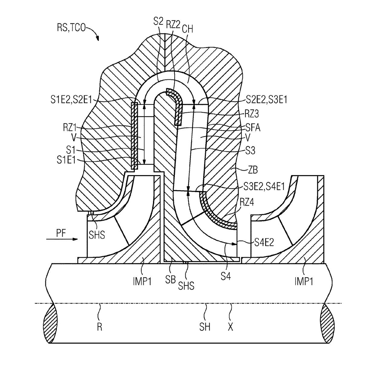
Return stage of a multi-stage turbocompressor or turboexpander having rough wall surfaces
- Summary
- Abstract
- Description
- Claims
- Application Information
AI Technical Summary
Benefits of technology
Problems solved by technology
Method used
Image
Examples
Embodiment Construction
[0033]FIG. 1 shows a schematic longitudinal section through a return stage RS from a first impeller IMP1 to a second impeller IMP2 of a turbocompressor TCO.
[0034]The two impellers IMP1, IMP2 are component parts of a rotor R, the impellers IMP1, IMP2 being mounted in a force-fitting manner on a shaft SH extending along an axis X. The rotor R is surrounded by flow-guiding stationary components, of which here a return stage RS is shown. A multi-stage turbomachine generally comprises a plurality of return stages RS, which, as considered in the direction of flow from a first impeller IMP1, which, in the case of the turbocompressor TCO, axially sucks a process fluid PF and discharges it radially, deflect the process fluid PF by 180° following a radial diffuser section and guide it back radially inward and then deflect it in an axial direction, in order to feed the process fluid PF to the second impeller IMP2 located downstream.
[0035]The return stage generally comprises a blade base SB and...
PUM
 Abstract
Description
Claims
Application Information
 - R&D
- Intellectual Property
- Life Sciences
- Materials
- Tech Scout
- Unparalleled Data Quality
- Higher Quality Content
- 60% Fewer Hallucinations
Browse by: Latest US Patents, China's latest patents, Technical Efficacy Thesaurus, Application Domain, Technology Topic, Popular Technical Reports.
© 2025 PatSnap. All rights reserved.Legal|Privacy policy|Modern Slavery Act Transparency Statement|Sitemap|About US| Contact US: help@patsnap.com


