
Circuit breaker with a gear having a dead point

a circuit breaker and dead point technology, applied in the direction of air break switch, high-tension/heavy-dress switch, contact mechanism, etc., can solve the problem of unideally matched movement of contacts

Active Publication Date: 2013-04-09
HITACHI ENERGY LTD
View PDF11 Cites 1 Cited by
  • Summary
  • Abstract
  • Description
  • Claims
  • Application Information

AI Technical Summary

Benefits of technology

The patent text describes a method to improve the speed control of a contact disconnection mechanism in a circuit breaker. The method allows for a faster movement of the second contact piece only after contact disconnection, which saves energy, reduces wear and physical space, and improves overall efficiency. The disclosure also includes an apparatus for carrying out the method steps, such as a gear for installation and use in a circuit breaker.

Problems solved by technology

The known switches from the prior art cause, however, a movement of the contacts which are not ideally matched to one another in various respect.
Furthermore, gears or transmissions for these switches can in some cases be implemented only by occupying a considerable amount of space which is disadvantageous, especially in the case of gas-blast circuit breakers.

Method used


Image

  • Circuit breaker with a gear having a dead point
  • Circuit breaker with a gear having a dead point
  • Circuit breaker with a gear having a dead point

Examples


Embodiment Construction

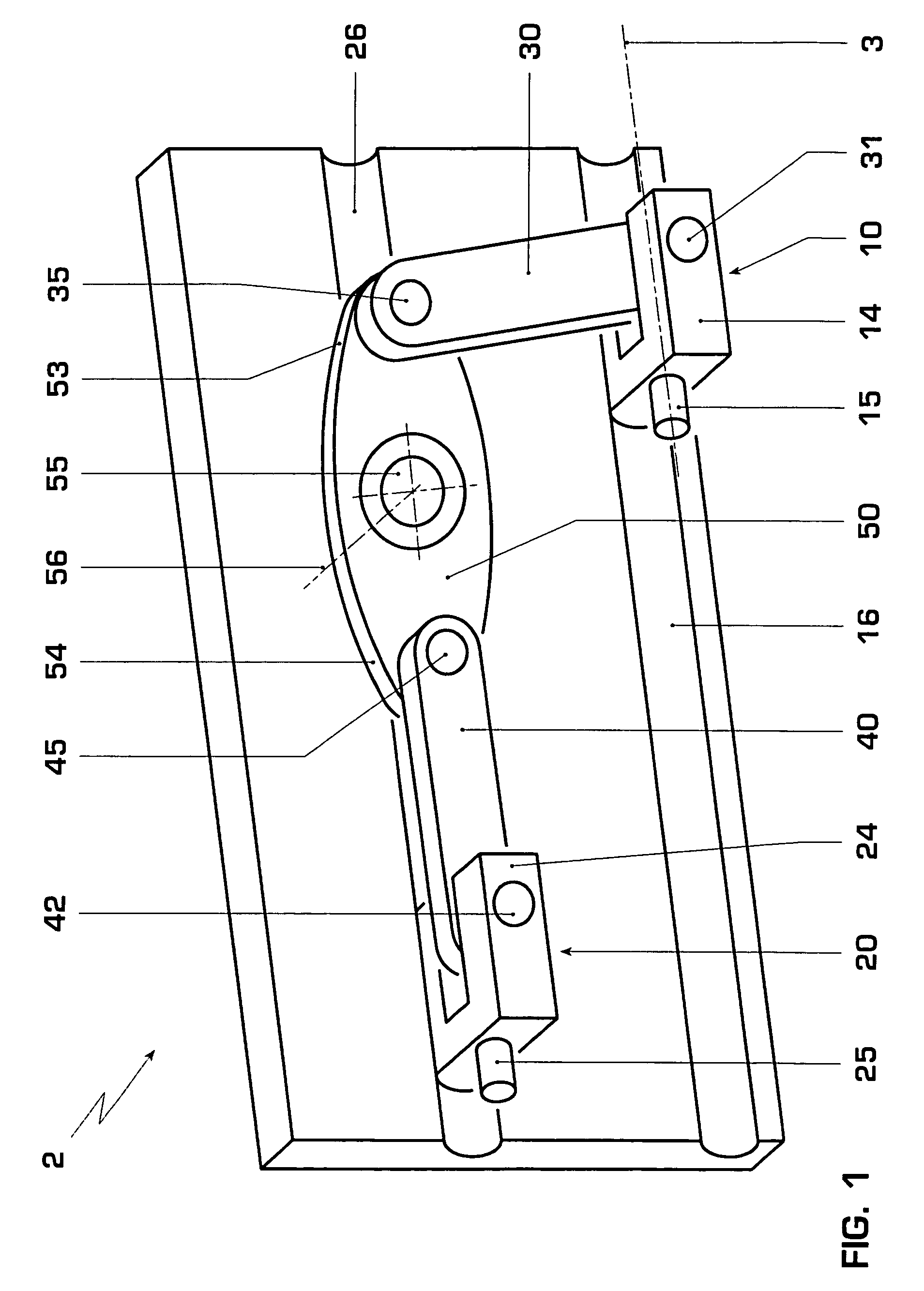
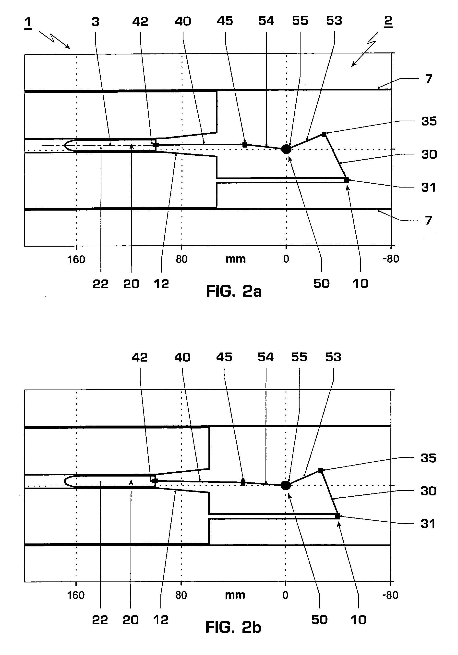
[0018]According to a first aspect of the disclosure, an electrical circuit breaker with a specific double movement of the contacts is made available. The circuit breaker comprises a first switching piece, typically with a first arcing contact, in particular a tulip, and a second contact piece typically with a second arcing contact, in particular a pin. The circuit breaker furthermore comprises a drive for moving the first contact piece in a first movement range along a switching axis, that is to say essentially parallel to or anti-parallel to the switching axis, in particular relative to an enclosure, and a gear for transferring the movement of the first contact piece to a movement of the second contact piece. The first movement range comprises a contact-subrange and a disconnecting-subrange. The arcing contacts make contact with one another, that is to say a mechanical and electrical contact is provided, when the first contact piece is in the contact-subrange, and they are mechanic...


PUM


Abstract

An electrical circuit breaker has a first contact piece which can be moved in a first movement range along a switching axis and has an arcing contact, a second contact piece which can move along the switching axis and which has a further arcing contact, a drive for moving the first contact piece and a gear for transferring the movement of the first contact piece to the second contact piece. The gear has a first dead point which is passed through on the output drive side by the gear during the movement of the first contact piece in the first movement range.

Description

RELATED APPLICATION[0001]This application claims priority under 35 U.S.C. §119 to European Patent Application No. 06405511.4 filed in the European Patent Office on 11 Dec. 2006, the entire contents of which are hereby incorporated by reference in their entireties.TECHNICAL FIELD[0002]The present disclosure relates in general to electrical circuit breakers, and in particular to electrical circuit breakers with a double drive. The disclosure also relates to methods for contact disconnection in an electrical circuit breaker.BACKGROUND INFORMATION[0003]Switches in which an arcing contact for example a quenching tulip, are moved away from a further arcing contact, for example, a pin, in order to disconnect an electrical connection are known from the prior art. Switches are also known in which two arcing contacts are moved in opposite directions.[0004]By way of example, EP 0 809 269 discloses a high-voltage circuit breaker having two movable arcing contact pieces which are coaxially oppos...

Claims


Application Information

Patent Timeline
Patent Type & Authority Patents(United States)
IPC IPC(8): H01H33/90
CPCH01H33/904H01H2033/028
Inventor HUNGER, OLAFNUFER, JURG
Owner HITACHI ENERGY LTD
Learn More