
Method and Apparatus for Open-Air Pulsed Laser Deposition

a pulsed laser and open-air technology, applied in the direction of chemical vapor deposition coating, vacuum evaporation coating, coating, etc., can solve the problems of oxidation and other highly undesirable chemical transformations, high cost and limited use of pulsed laser in vacuum

Active Publication Date: 2017-08-17
DILLARD UNIVERSITY
View PDF5 Cites 1 Cited by
  • Summary
  • Abstract
  • Description
  • Claims
  • Application Information

AI Technical Summary

Benefits of technology

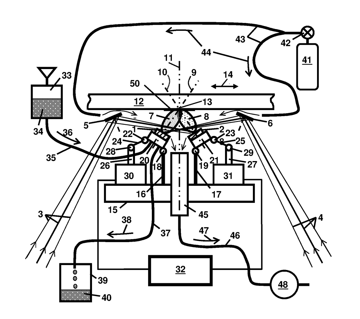
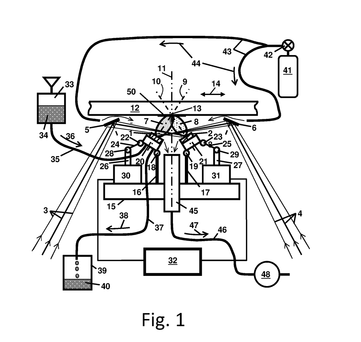
The present invention is a method and apparatus for depositing films on a substrate using pulsed laser beams. The process is carried out in an open-air environment without the need for a vacuum chamber. A low pressure zone is maintained between the targets and the substrate using a vacuum pump to shield it from ambient oxygen. The targets may be remotely tilted to provide optimal plume overlapping on the substrate. The plumes are isolated from ambient oxygen using a shield of continuously flowing inert gas. The invention allows for the deposition of materials that are reactive with respect to oxygen. The target may be made of a polymer solution frozen with circulating liquid nitrogen. The technical effects of the invention include the ability to deposit films on large substrates using a simple and flexible method.

Problems solved by technology

However, PLD in the vacuum is expensive and is limited to the substrates of small size that can fit in the vacuum chamber.
1) At atmospheric pressure the mean free path of the ions of the target material knocked out by a high-energy laser beam from a target does not exceed one or two millimeters. This is due to very many collisions of the plume plasma ions with the molecules of the gases in ambient air.
2) PLD in ambient air has and a risk of chemical reaction of the plume ions with atmospheric oxygen leading to oxidation and other highly undesirable chemical transformations of the target material being deposited on the substrate.

Method used


Image

  • Method and Apparatus for Open-Air Pulsed Laser Deposition
  • Method and Apparatus for Open-Air Pulsed Laser Deposition

Examples


Embodiment Construction

[0015]The present disclosure pertains to open air laser deposition of thin films that may eliminate the need for operation in a vacuum chamber, potentially reducing the cost of industrial applications and allowing film depositions on large irregular objects as well as making more practical the possibility of field applications.

[0016]A. Aspects of the Invention

[0017]Aspects of the invention relate to addressing multiple performance characteristics, namely:

[0018]1) To increase the distance between the target and the substrate and provide more room for the adjustment of laser beam direction and the target orientation. As a result—to make possible to accommodate multiple targets and multiple laser beams with the plume direction adjustment for multi-beam multi-target PLD of composite films.

[0019]2) To isolate the ions of the target plume from atmospheric oxygen. So PLD in open air will not be limited to the materials (mainly, gold and diamond) that do not react with oxygen.

[0020]3) To im...


PUM

PropertyMeasurementUnit
Pressureaaaaaaaaaa
Flow rateaaaaaaaaaa
Areaaaaaaaaaaa

Abstract

A method and apparatus for open-air pulsed laser deposition with a low pressure zone maintained between the targets and the substrate by pumping the ambient gas out with a vacuum pump. The zone between the targets and the substrate may be shielded from ambient oxygen with an inert gas flowing from outside. The films can be deposited on a large substrate, which may be freely translated with respect to the targets. The apparatus may accommodate multiple pulsed laser beams and multiple targets. The targets may be remotely tilted in order to provide optimal plume overlapping on the substrate. At least one target may be deposited using the matrix assisted pulsed laser evaporation process. The target may be made of a polymer solution frozen with circulating liquid nitrogen.

Description

RELATED APPLICATIONS[0001]This application claims the benefit under 35 USC 119(e) of provisional application Ser.No. 62 / 389,086 Titled “Method and apparatus for open-air multi-beam multi-target pulsed laser deposition,” filed Feb. 17, 2016 by Darwish et al.[0002]This application may have related disclosure to that found in U.S. application Ser. No. 14 / 158,567, titled “Multiple Beam Pulsed Laser Deposition Of Composite Films” filed 17 Jan. 2014 by Darwish et al, published 14 Aug. 2014, US2014 / 0227461A1; and U.S. application Ser. No. 14 / 506,685, titled “Multiple Beam Pulsed Laser Deposition Of Composite Films” filed 5 Oct. 2014 by Darwish et al., publication US 2016 / 0230265 A1, Aug. 11, 2016.[0003]All of the above listed US Patent and Patent Application and Publication documents are hereby incorporated herein by reference in their entirety.BACKGROUND[0004]Technical Field[0005]The present invention pertains generally to the field of deposition of thin films, more particularly, to depos...

Claims


Application Information

Patent Timeline
IPC IPC(8): C23C14/28
CPCC23C14/28C23C14/06C23C14/225C23C14/3485C23C16/483
Inventor DARWISH, ABDALLASARKISOV, SERGEY
Owner DILLARD UNIVERSITY
Learn More