
Composite fiber filter comprising nan0-materials, and manufacturing method and apparatus thereof

a composite fiber and filter technology, applied in the field of filter units, can solve the problems of high production cost, inability to filter out nanometer-sized fine contaminant particles, and difficulty in manufacturing nano-scale fibers having a diameter of less than 1 m, and achieve high functionality, antibacterial activity, and high efficiency.

Inactive Publication Date: 2008-09-11
LEE BONG DAE +2
View PDF0 Cites 81 Cited by
  • Summary
  • Abstract
  • Description
  • Claims
  • Application Information

AI Technical Summary

Benefits of technology

[0009]It is therefore an object of the present invention to provide a composite fiber filter having high efficiency, high functionality and antibacterial activity, which comprises a composite of nanofibers and microfibers, as well as an apparatus and method for producing said composite fiber filter.
[0010]Another object of the present invention is to provide an apparatus and method by which a composite fiber filter comprising a composite of nanofibers and microfibers can be produced with high productivity.
[0011]Still another object of the present invention is to provide a composite fiber filter for water purification, having high efficiency, high functionality and antibacterial activity, as well as an apparatus and method for manufacturing the same.

Problems solved by technology

However, the microfibers manufactured in this manner have a diameter of about 5-500 μm and it is difficult to manufacture nano-scale fibers having a diameter of less than 1 μm.
Accordingly, with a filter made of such microfibers, micrometer-sized contaminant particles can be filtered out, but it is in fact impossible to filter out nanometer-sized fine contaminant particles.
However, in producing a filter using nanofibers, a very high production cost is incurred and it is not easy to adjust various production conditions.
For this reason, it is impossible to produce and distribute the filter made of nanofibers at a relatively low cost.
In manufacturing a filter using nanofibers, problems of differential pressure and filtration efficiency, in addition to the above-mentioned high cost, can occur.

Method used


Image

  • Composite fiber filter comprising nan0-materials, and manufacturing method and apparatus thereof
  • Composite fiber filter comprising nan0-materials, and manufacturing method and apparatus thereof
  • Composite fiber filter comprising nan0-materials, and manufacturing method and apparatus thereof

Examples


Embodiment Construction

[0031]Hereinafter, preferred embodiments of the present invention will be described in detail with reference to the accompanying drawings. It is noted that like elements throughout the drawings will be denoted by like reference numerals, if possible. Also, the detailed description of known functions and constructions unnecessarily obscuring the subject matter of the present invention will be avoided.

[0032]In the present invention, a novel type of highly efficient, highly functional composite fiber filter, which has fine pores and, at the same time, does not cause an increase in pressure, is manufactured by combining a nanofiber nonwoven fabric with microfibers.

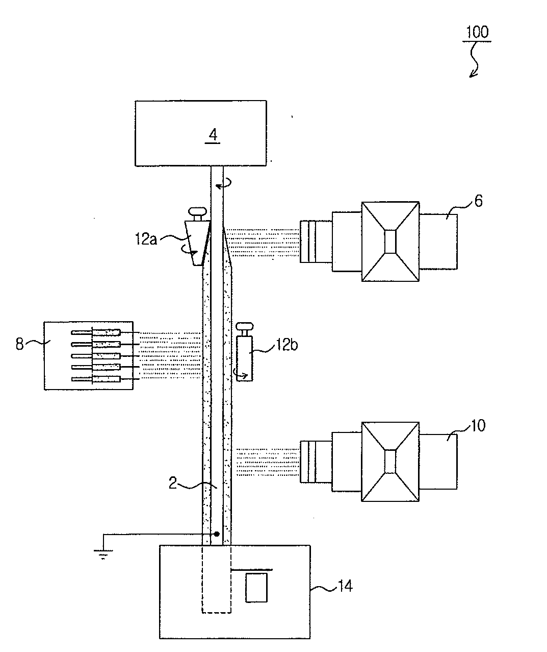
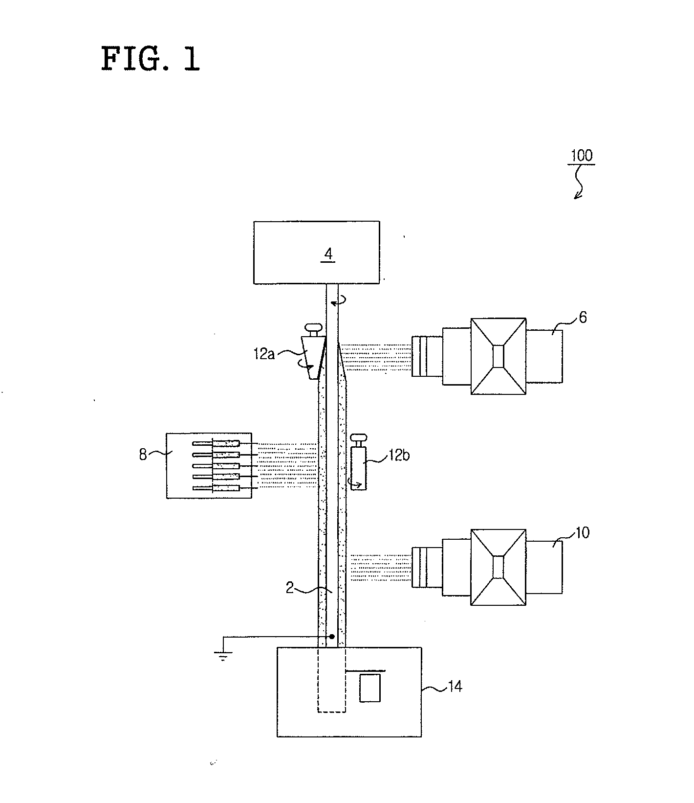
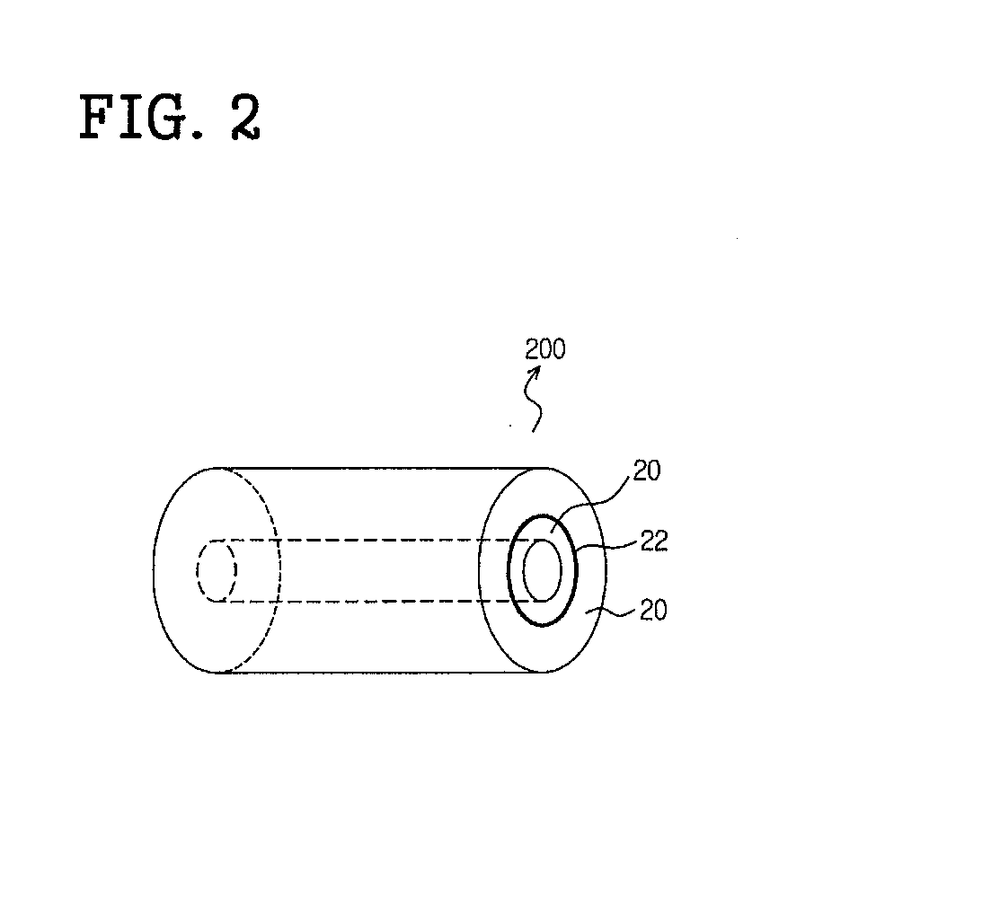
[0033]FIG. 1 shows the construction of a composite fiber filter-manufacturing apparatus 100 according to an embodiment of the present invention, and FIG. 2 is a perspective view of a cylindrical composite fiber filter 200 manufactured using the composite fiber filter-manufacturing apparatus 100 according to the embodiment of t...


PUM

PropertyMeasurementUnit
Fractionaaaaaaaaaa
Diameteraaaaaaaaaa
Diameteraaaaaaaaaa

Abstract

Disclosed herein is a method for manufacturing a composite fiber filter having high efficiency and high functionality, the method comprising: melt-spinning microfiber yarns on a forming rod, which is made of a conductive material, grounded at one end thereof and rotatably driven, using a melt-spinning device, to form on the forming layer a microfiber layer consisting of the microfiber yarns; and electrospinning on the microfiber layer an electrospinnable polymer solution having a given dielectric constant, using an electrospinning device, so as to form on the microfiber layer a nanofiber layers consisting of nanofiber yarns, wherein the microfiber yarns of the microfiber layer and the nanofiber yarns of the nanofiber layer contain silver nanoparticles so as to have an antibacterial function.

Description

BACKGROUND OF THE INVENTION[0001]1. Field of the Invention[0002]The present invention relates to a filter unit, and more particularly to an apparatus and method of manufacturing a composite fiber filter having high efficiency, high-functionality and antibacterial activity by combining nanofibers with microfibers.[0003]2. Background of the Related Art[0004]Generally, most microfibers are manufactured through spinning processes such as melting spinning, dry spinning or wet spinning, that is, by extruding and spinning a polymer solution through fine holes by mechanical forces. However, the microfibers manufactured in this manner have a diameter of about 5-500 μm and it is difficult to manufacture nano-scale fibers having a diameter of less than 1 μm. Accordingly, with a filter made of such microfibers, micrometer-sized contaminant particles can be filtered out, but it is in fact impossible to filter out nanometer-sized fine contaminant particles.[0005]Thus, various methods for manufact...

Claims


Application Information

Patent Timeline
IPC IPC(8): D01D5/08B01D39/00B01D39/14B01D39/16B32B5/26D01D5/04D01F1/10D04H1/559D04H1/728D04H3/16
CPCB01D39/1623Y10T156/1051B01D2239/0258B01D2239/0442B01D2239/065B01D2239/10D01D5/0061D01D5/08D01F1/103D01F6/38D01F6/60D04H1/43D04H1/4334D04H1/4374D04H1/56D04H1/72D04H1/728D04H1/732D04H3/07D04H3/16B01D2239/025
Inventor LEE, BONG DAEKANG, INN KYUKWON, OH HYEONG
Owner LEE BONG DAE
Learn More