
Ignition system and method for controlling an ignition system for a spark-ignited internal combustion engine

Active Publication Date: 2017-07-27
ROBERT BOSCH GMBH
View PDF5 Cites 2 Cited by
  • Summary
  • Abstract
  • Description
  • Claims
  • Application Information

AI Technical Summary

Benefits of technology

The patent describes a system for controlling the ignition timing and a boost converter in an internal combustion engine. The system uses multiple control signals that can be transmitted through a simple network, resulting in cost and weight savings. The control signals can influence various parameters of the boost converter and ignition system, such as ignition timing, power level, and time delay. This allows for increased efficiency and lower fuel consumption of the engine. The system is easily evaluutable and implementable without intervention. Overall, the patent provides a technical solution for enhancing the performance and reducing the fuel consumption of internal combustion engines.

Problems solved by technology

However, there are still no proposals known in the related art for the corresponding control.

Method used


Image

  • Ignition system and method for controlling an ignition system for a spark-ignited internal combustion engine
  • Ignition system and method for controlling an ignition system for a spark-ignited internal combustion engine
  • Ignition system and method for controlling an ignition system for a spark-ignited internal combustion engine

Examples


Embodiment Construction

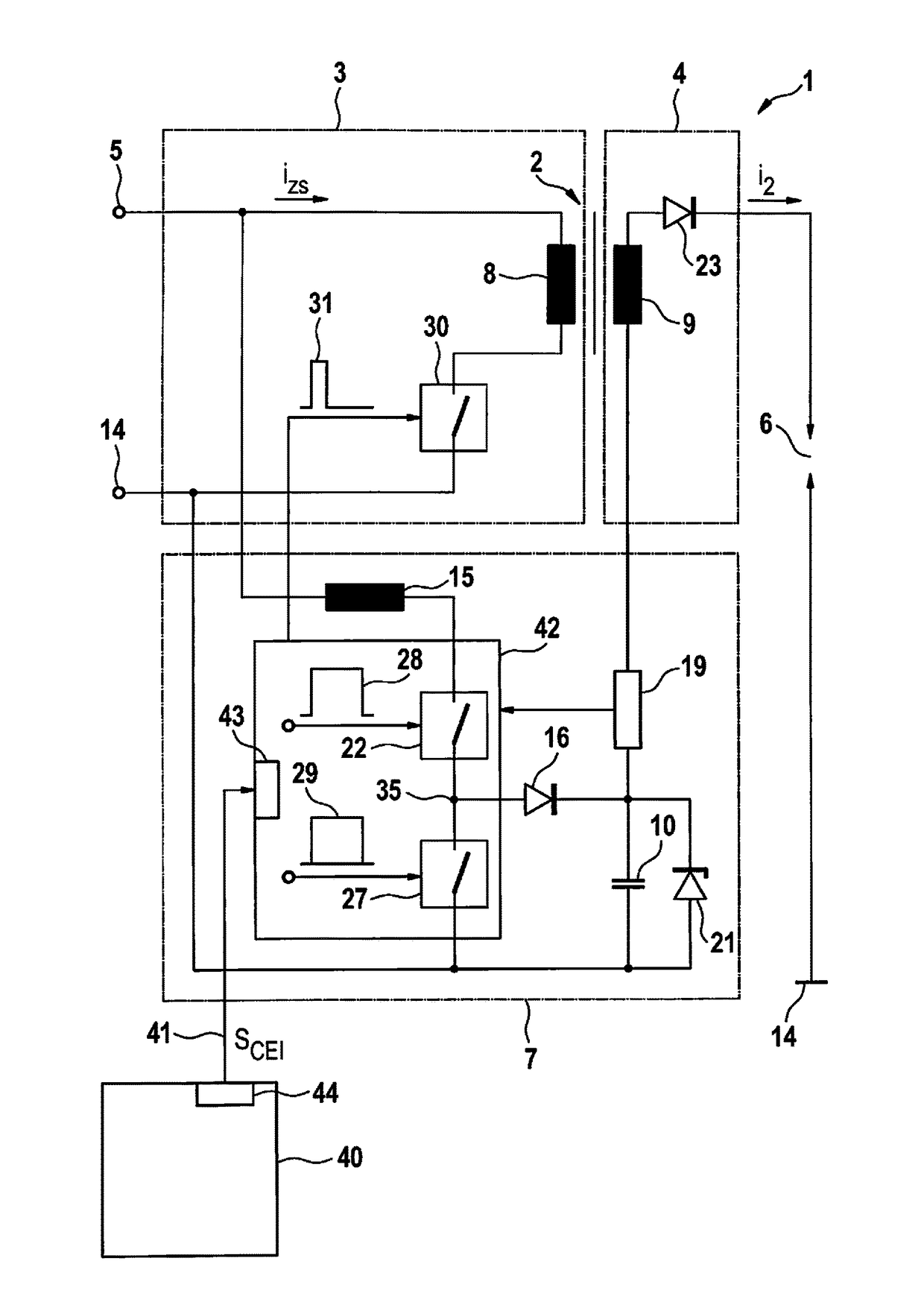
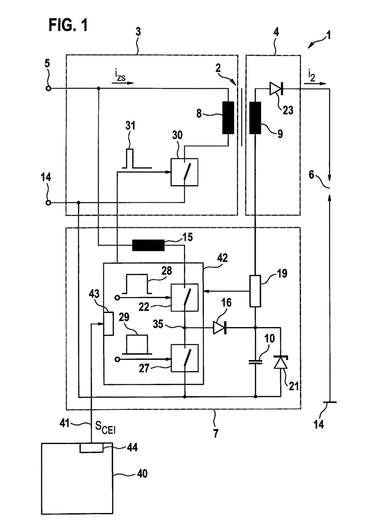
[0027]FIG. 1 shows a circuit of an ignition system 1, which includes a step-up transformer 2 as a high voltage generator, the primary side 3 of which may be supplied with electrical power from an electrical energy source 5 via a first switch 30. Secondary side 4 of step-up transformer 2 is supplied with electrical power via an inductive coupling of primary coil 8 and secondary coil 9, and includes a conventional diode 23 for suppressing a switch-on spark, this diode 23 being alternatively replaceable by diode 21. A spark gap 6 is provided in a loop with secondary coil 9 and diode 23 to ground 14, via which the ignition current i2 is intended to ignite the combustible gas mixture. According to the present invention, a boost converter 7 is provided between electrical energy source 5 and secondary side 4 of step-up transformer 2. For this purpose, an inductance 15 is connected via a switch 22 and a diode 16 to a capacitance 10, the one end of which is connected to secondary coil 9 and ...


PUM


Abstract

An ignition system and a method for controlling an ignition system for a spark-ignited internal combustion engine are described, having a primary voltage generator for generating an ignition spark and a boost converter for maintaining an ignition spark. The method includes sending a signal from an engine control unit to the ignition system, in order to determine a predetermined ignition timing for triggering an ignition spark, sending an additional signal from the engine control unit to the ignition system, in order to determine a predetermined additional ignition timing for triggering an additional ignition spark, and sending a control signal for influencing the operating mode of the boost converter from the engine control unit to the ignition system between the signal and the additional signal.

Description

FIELD[0001]The present invention relates to an ignition system for an internal combustion engine. The present invention relates, in particular, to an ignition system for internal combustion engines, in which increased demands exist as a result of (high) supercharging and diluted mixtures which are difficult to ignite (λ>>1, lean layer concepts, high EGR rates).BACKGROUND INFORMATION[0002]Great Britain Patent No. GB717676 describes a step-up transformer for an ignition system, in which a circuit element controlled by a vibration switch in the manner of a boost converter is used to supply a spark, generated via the step-up transformer, with electrical power.[0003]PCT Application No. WO 2009 / 106100 A1 describes a circuit configuration designed corresponding to a high-voltage capacitor ignition system, in which energy stored in a capacitor is conducted, on the one hand, to the primary side of a transformer and, on the other hand, to a spark gap via a bypass having a diode.[0004]U....

Claims


Application Information

Patent Timeline
IPC IPC(8): F02P3/045F02P9/00F02P3/04
CPCF02P3/045F02P9/007F02P3/0407F02P5/00F02D41/266F02P2017/121F02P15/10
Inventor SKOWRONEK, TIMPAWLAK, THOMASEICHHORN, JOERGSINZ, WOLFGANG
Owner ROBERT BOSCH GMBH
Learn More