Ignition system and method for controlling an ignition system for a spark-ignited internal combustion engine

a technology of internal combustion engine and ignition system, which is applied in the direction of electric control, machines/engines, mechanical apparatus, etc., can solve the problems of no proposals known in the related art for corresponding control, and achieve the effect of being particularly simple circuitwise and being easily evaluabl

Active Publication Date: 2018-07-31
ROBERT BOSCH GMBH
View PDF20 Cites 0 Cited by
  • Summary
  • Abstract
  • Description
  • Claims
  • Application Information

AI Technical Summary

Benefits of technology

[0011]The signals and the at least one control signal, which is sent between the signals to the ignition system, may pass via an identical signal (for example, an electrical lead) from the engine control unit to the ignition system. This represents a particularly simple topology, which entails material savings, cost savings and weight advantages. The connection of the engine control unit to the ignition system or the transmission of information between the two units may also take place in a simple manner (for example, according to the related art).
[0012]The control signal may essentially have a high level identical to the respective signal for determining the ignition timing. Alternatively or in addition, the control signal may have a reduced electrical level compared to the signals for determining the ignition timing, for example, a so-called “low level”, which may be understood as a pause between two high-level signals. This simplifies the electrical evaluation of the signals and enhances the interference resistance to interspersed electromagnetic signals.
[0014]The operating mode of the boost converter may, for example, result via a (chronological) position of an edge (for example, a rising edge of a high level and / or a falling edge of a high level). Both edges of a shared level of the control signal may also be used to influence the operating mode of the boost converter. Such an evaluation is circuitry-wise particularly simple and possible without interferences.
[0015]Alternatively or in addition, the operating mode of the boost converter may also be influenced by an evaluation of a number of pulses, which are transmitted as part of the control signal to the ignition system. For example, rising edges and / or falling edges of pulses may be counted and the operating mode of the boost converter may be changed in a predefined manner in response to the ascertained number. For example, the number of pulses may decide about a power level to be output and / or about a time delay of a start of operation of the boost converter relative to the switch-on instant of the primary voltage generator. This type of information transmission is also circuitry-wise easily evaluatable and implementable unsusceptible to interference.
[0018]Multiple control signals may, of course, also be transmitted between the first signal and the additional signal, in order to induce the ignition system to influence additional parameters of the operating mode of the boost converter. Each of the aforementioned parameters may be adapted individually and / or in combination with additional parameters via individual edges and / or levels and / or numbers and / or time durations of control signals. This results in far-reaching possibilities for increasing the efficiency of an internal combustion engine equipped with the ignition system and for lowering its fuel consumption. In other words, each additional control signal may define one or multiple of the aforementioned parameters of the boost converter or of the ignition system.

Problems solved by technology

However, there are still no proposals known in the related art for the corresponding control.

Method used


Image

  • Ignition system and method for controlling an ignition system for a spark-ignited internal combustion engine
  • Ignition system and method for controlling an ignition system for a spark-ignited internal combustion engine
  • Ignition system and method for controlling an ignition system for a spark-ignited internal combustion engine

Examples


Embodiment Construction

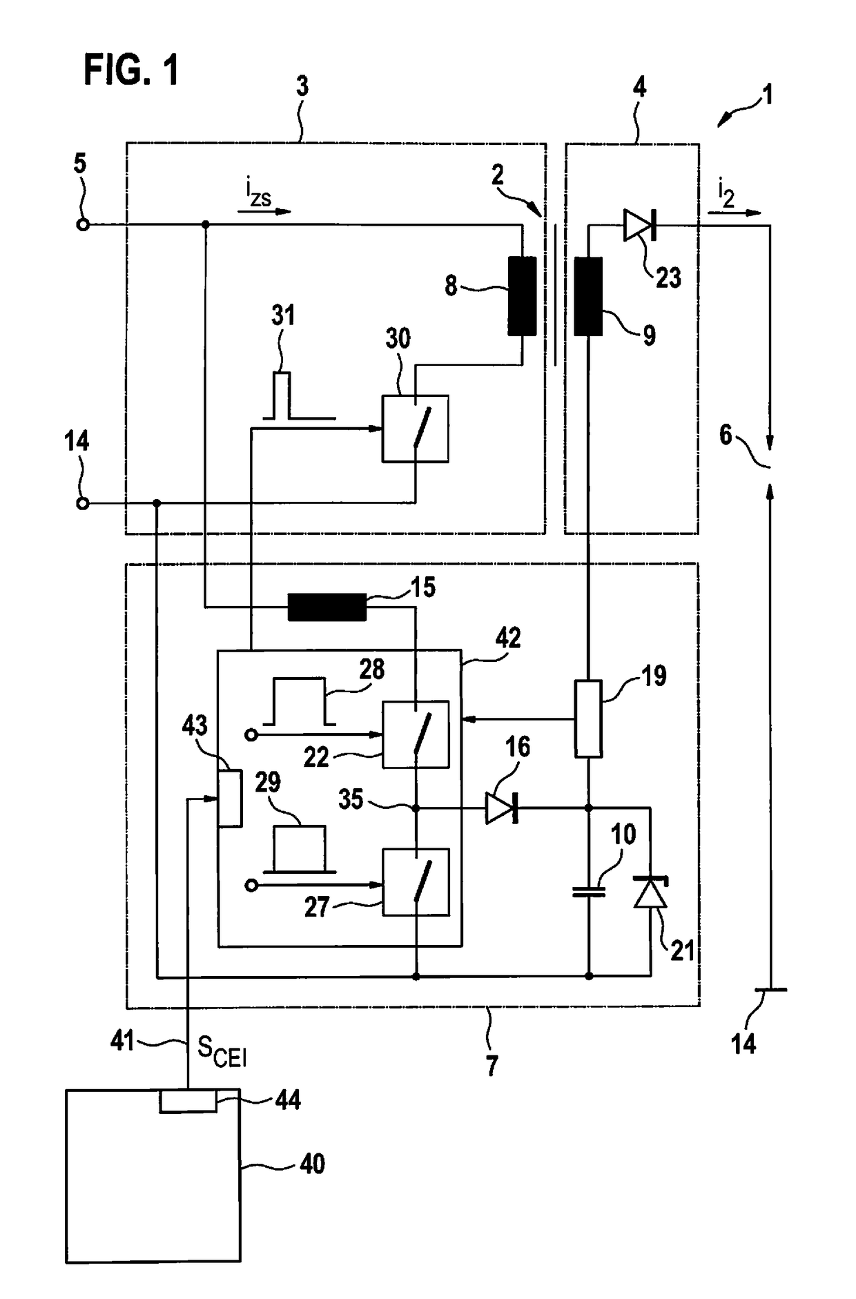
[0027]FIG. 1 shows a circuit of an ignition system 1, which includes a step-up transformer 2 as a high voltage generator, the primary side 3 of which may be supplied with electrical power from an electrical energy source 5 via a first switch 30. Secondary side 4 of step-up transformer 2 is supplied with electrical power via an inductive coupling of primary coil 8 and secondary coil 9, and includes a conventional diode 23 for suppressing a switch-on spark, this diode 23 being alternatively replaceable by diode 21. A spark gap 6 is provided in a loop with secondary coil 9 and diode 23 to ground 14, via which the ignition current i2 is intended to ignite the combustible gas mixture. According to the present invention, a boost converter 7 is provided between electrical energy source 5 and secondary side 4 of step-up transformer 2. For this purpose, an inductance 15 is connected via a switch 22 and a diode 16 to a capacitance 10, the one end of which is connected to secondary coil 9 and ...


PUM


Abstract

An ignition system and a method for controlling an ignition system for a spark-ignited internal combustion engine are described, having a primary voltage generator for generating an ignition spark and a boost converter for maintaining an ignition spark. The method includes sending a signal from an engine control unit to the ignition system, in order to determine a predetermined ignition timing for triggering an ignition spark, sending an additional signal from the engine control unit to the ignition system, in order to determine a predetermined additional ignition timing for triggering an additional ignition spark, and sending a control signal for influencing the operating mode of the boost converter from the engine control unit to the ignition system between the signal and the additional signal.

Description

FIELD[0001]The present invention relates to an ignition system for an internal combustion engine. The present invention relates, in particular, to an ignition system for internal combustion engines, in which increased demands exist as a result of (high) supercharging and diluted mixtures which are difficult to ignite (λ>>1, lean layer concepts, high EGR rates).BACKGROUND INFORMATION[0002]Great Britain Patent No. GB717676 describes a step-up transformer for an ignition system, in which a circuit element controlled by a vibration switch in the manner of a boost converter is used to supply a spark, generated via the step-up transformer, with electrical power.[0003]PCT Application No. WO 2009 / 106100 A1 describes a circuit configuration designed corresponding to a high-voltage capacitor ignition system, in which energy stored in a capacitor is conducted, on the one hand, to the primary side of a transformer and, on the other hand, to a spark gap via a bypass having a diode.[0004]U....

Claims


Application Information

Patent Timeline
Patent Type & Authority Patents(United States)
IPC IPC(8): F02P3/045F02P9/00F02P3/04
CPCF02P3/045F02P9/007F02P3/0407F02D41/266F02P5/00F02P15/10F02P2017/121
Inventor SKOWRONEK, TIMPAWLAK, THOMASEICHHORN, JOERGSINZ, WOLFGANG
Owner ROBERT BOSCH GMBH
Why Eureka
Try Eureka