Chemical-free production of graphene materials

a graphene material, chemical-free technology, applied in the field of graphene materials, can solve the problems of high energy consumption of the process, inability to mass produce ngps, and inability to meet the requirements of heat- and solution-induced exfoliation, so as to maximize burnout, maximize solubility, and maximize the effect of solubility

Active Publication Date: 2017-06-08
GLOBAL GRAPHENE GRP INC
View PDF3 Cites 22 Cited by
  • Summary
  • Abstract
  • Description
  • Claims
  • Application Information

AI Technical Summary

Benefits of technology

[0063]One significant advantage of the present invention as compared to prior art is flexibility of selecting carrier materials. There are many opportunities to use pre-consumer, or post-consumer waste material as the carrier, diverting this material from disposal by landfill or incineration. Nut shells, rice husks, shredded tires, and ground co-mingled recycled plastic are all possible cost effective carrier materials for the production of graphene. An additional advantage of this flexibility is the carrier material can be chosen to maximize burnout or to maximize solubility in low cost, environmentally friendly, and lower health hazard hazardous solvents. For example, a carrier material readily soluble in acetone may be chosen over a carrier material requiring methyl ethyl ketone for removal, and will facilitate the scale up of a cost effective manufacturing process.
[0064]An important advantage of the present invention is the opportunity to use multiple carrier removal methods. For example, melting at 200° may be used to remove 99% of a wax carrier material, followed by burnout at 1000° C. As another example, solvent removal may be used to remove the majority of a polymer carrier material, followed by burnout at 1200° C. The combining of carrier removal processes allows for cost effective re-use of carrier materials, while also achieving high levels of purity for the final graphene produced.
[0065]In a desired embodiment, the presently invented method is carried out in an automated and / or continuous manner. For instance, as illustrated in FIG. 3, the mixture of graphite particles and solid carrier particles (plus optional impacting balls) is delivered by a conveyer belt 12 and fed into a continuous ball mill 14. After ball milling to form graphene-coated solid carrier particles, the product mixture (possibly also containing some residual graphite particles and optional impacting balls) is discharged from the ball mill apparatus 14 into a screening device (e.g. a rotary drum 16) to separate graphene-coated solid carrier particles from residual graphite particles (if any) and impacting balls (if any). This separation operation may be assisted by a, magnetic separator 18 if the impacting balls are ferromagnetic (e.g. balls of Fe, Co, Ni, or Mn-based metal). The graphene-coated carrier particles may be delivered into a combustion chamber 20, if the solid carrier can be burned off (e.g. plastic beads, rubber particles, and wax particles, etc.). Alternatively, these particles can be discharged into a dissolving chamber for dissolving the carrier particles (e.g. plastic beads). The product mass can be further screened in another (optional) screening device 22, a powder classifier or cyclone 24, and / or an electrostatic separator 26. These procedures can be fully automated.
[0066]Graphene sheets transferred to carrier solid particle surfaces have a significant proportion of surfaces that correspond to the edge planes of graphite crystals. The carbon atoms at the edge planes are reactive and must contain some heteroatom or group to satisfy carbon valency. There are many types of functional groups (e.g. hydroxyl and carboxylic) that are naturally present at the edge or surface of graphene nano platelets produced through transfer to a solid carrier particle. The impact-induced kinetic energy experienced by the carrier particles are of sufficient energy and intensity to chemically activate the edges and even surfaces of graphene sheets coated on carrier particle surfaces (e.g. creating highly active sites or free radicals). Provided that certain chemical species containing desired chemical function groups (e.g. —NH2, Br—, etc.) are included in the impacting chamber, these functional groups can be imparted to graphene edges and / or surfaces. In other words, production and chemical functionalization of graphene sheets can be accomplished concurrently by including appropriate chemical compounds in the impacting chamber. In summary, a major advantage of the present invention over other processes is the simplicity of simultaneous production and modification of surface chemistry.
[0067]Graphene platelets derived by this process may be functionalized through the inclusion of various chemical species in the impacting chamber. In each group of chemical species discussed below, we selected 2 or 3 chemical species for functionalization studies.
[0068]In one preferred group of chemical agents, the resulting functionalized NGP may broadly have the following formula(e): [NGP]-Rm, wherein m is the number of different functional group types (typically between 1 and 5), R is selected from SO3H, COOH, NH2, OH, R′CHOH, CHO, CN, COCl, halide, COSH, SH, COOR′, SR′, SiR′3, R″, Li, AlR′2, Hg—X, TlZ2 and Mg—X; wherein y is an integer equal to or less than 3, R′ is hydrogen, alkyl, aryl, cycloalkyl, or aralkyl, cycloaryl, or poly(alkylether), R″ is fluoroalkyl, fluoroaryl, fluorocycloalkyl, fluoroaralkyl or cycloaryl, X is halide, and Z is carboxylate or trifluoroacetate.

Problems solved by technology

There are several major problems associated with this conventional chemical production process:(1) The process requires the use of large quantities of several undesirable chemicals, such as sulfuric acid, nitric acid, and potassium permanganate or sodium chlorate.(2) The chemical treatment process requires a long intercalation and oxidation time, typically 5 hours to five days.(3) Strong acids consume a significant amount of graphite during this long intercalation or oxidation process by “eating their way into the graphite” (converting graphite into carbon dioxide, which is lost in the process).
It is not unusual to lose 20-50% by weight of the graphite material immersed in strong acids and oxidizers.(4) The thermal exfoliation requires a high temperature (typically 800-1,200° C.) and, hence, is a highly energy-intensive process.(5) Both heat- and solution-induced exfoliation approaches require a very tedious washing and purification step.
During the high-temperature exfoliation, the residual intercalate species retained by the flakes decompose to produce various species of sulfuric and nitrous compounds (e.g., NOx and SOx), which are undesirable.
The process must be carefully conducted in a vacuum or an extremely dry glove box environment since pure alkali metals, such as potassium and sodium, are extremely sensitive to moisture and pose an explosion danger.
This process is not amenable to the mass production of NGPs.
However, these processes are not suitable for mass production of isolated graphene sheets for composite materials and energy storage applications.
This is a slow process that thus far has produced very small graphene sheets.

Method used


Image

  • Chemical-free production of graphene materials
  • Chemical-free production of graphene materials
  • Chemical-free production of graphene materials

Examples


example 1

NGP (Graphene Sheets) from Flake Graphite Via Polypropylene Powder-Based Carrier

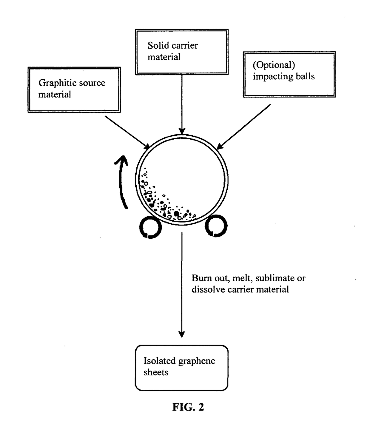
[0076]In an experiment, 1 kg of polypropylene pellets, 50 grams of flake graphite, 50 mesh (average particle size 0.18 mm; Asbury Carbons, Asbury N.J.) and 250 grams of magnetic stainless steel pins (Raytech Industries, Middletown Conn.) were placed in a ball mill container. The ball mill was operated at 300 rpm for 4 hours. The container lid was removed and stainless steel pins were removed via a magnet. The polymer carrier material was found to be coated with a dark carbon layer. Carrier material was placed over a 50 mesh sieve and a small amount of unprocessed flake graphite was removed. Coated carrier material was then placed in a crucible in a vented furnace at 600° C. After cooling down, the furnace was opened to reveal a crucible full of isolated graphene sheet powder.

[0077]Although polypropylene (PP) is herein used as an example, the carrier material for making isolated graphene sheets is not lim...

example 2

Expanded Graphite Via ABS Polymer

[0078]In an experiment, 100 grams of ABS pellets, as solid carrier material particles, were placed in a 16 oz plastic container along with 5 grams of expanded graphite. This container was placed in an acoustic mixing unit (Resodyn Acoustic mixer), and processed for 30 minutes. After processing, carrier material was found to be coated with a thin layer of carbon. Carrier material was placed in acetone and subjected to ultrasound energy to speed dissolution of the ABS. The solution was filtered using an appropriate filter and washed four times with additional acetone. Subsequent to washing, filtrate was dried in a vacuum oven set at 60° C. for 2 hours.

example 3

lized Graphene from Meso-Carbon Micro Beads (MCMBs) Via PLA

[0079]In one example, 100 grams of PLA pellets (carrier material) and 2 grams of MCMBs (China Steel Chemical Co., Taiwan) were placed in a vibratory ball mill, which also contains particles of magnetic stainless steel impactor and processed for 2 hours. Subsequently, DETA was added and the material mixture was processed for an additional 2 hours. The vibratory mill was then opened and the carrier material was found to be coated with a dark coating of graphene. The magnetic steel particles were removed with a magnet. The carrier material was rinsed with isopropyl alcohol and placed on a vacuum filter. The vacuum filter was heated to 160° C. and vacuum was applied, resulting in removal of the PLA.

[0080]In separate experiments, the following functional group-containing species were introduced to the graphene sheets produced: an amino acid, sulfonate group (—SO3H), 2-Azidoethanol, polyamide (caprolactam), and aldehydic group. In...


PUM

PropertyMeasurementUnit
temperatureaaaaaaaaaa
timeaaaaaaaaaa
timeaaaaaaaaaa

Abstract

A method of producing isolated graphene sheets directly from a graphitic material, comprising: a) mixing multiple particles of a graphitic material and multiple particles of a solid carrier material to form a mixture in an impacting chamber of an energy impacting apparatus; b) operating the impacting apparatus for peeling off graphene sheets from the graphitic material and transferring these graphene sheets to surfaces of solid carrier material particles to produce graphene-coated solid particles inside the impacting chamber; c) separating the graphene sheets from the solid carrier material particle surfaces to recover isolated graphene sheets. The method enables production of graphene sheets directly from a graphitic material without going through a chemical intercalation or oxidation procedure. The process is fast (hours as opposed to days of conventional processes), has low or no water usage, environmentally benign, cost effective, and highly scalable.

Description

FIELD OF THE INVENTION[0001]The present invention relates to the art of graphene materials and, in particular, to a method of producing isolated graphene sheets in an environmentally benign manner.BACKGROUND[0002]A single-layer graphene sheet is composed of carbon atoms occupying a two-dimensional hexagonal lattice. Multi-layer graphene is a platelet composed of more than one graphene plane. Individual single-layer graphene sheets and multi-layer graphene platelets are herein collectively called nano graphene platelets (NGPs) or graphene materials. NGPs include pristine graphene (essentially 99% of carbon atoms), slightly oxidized graphene (<5% by weight of oxygen), graphene oxide (≧5% by weight of oxygen), slightly fluorinated graphene (<5% by weight of fluorine), graphene fluoride ((≧5% by weight of fluorine), other halogenated graphene, and chemically functionalized graphene.[0003]NGPs have been found to have a range of unusual physical, chemical, and mechanical properties....

Claims


Application Information

Patent Timeline
Patent Type & Authority Applications(United States)
IPC IPC(8): C01B31/04B28B1/30
CPCB82Y40/00Y10S977/734B28B1/30C01B31/0469Y10S977/842C01B2204/04C01B32/19C01B32/194C01B2202/04C01B2202/02
Inventor ZHAMU, ARUNAJANG, BOR Z
Owner GLOBAL GRAPHENE GRP INC
Why Eureka
Try Eureka