
Spectroscopic Beam Profile Overlay Metrology

a beam profile and metrology technology, applied in the field ofmetrology systems and methods, can solve the problems of increasing system complexity, and limiting the throughput of such systems, so as to improve the accuracy and precision of overlay measuremen

Active Publication Date: 2017-03-23
KLA TENCOR TECH CORP
View PDF6 Cites 35 Cited by
  • Summary
  • Abstract
  • Description
  • Claims
  • Application Information

AI Technical Summary

Benefits of technology

This patent describes a system for accurately measuring the alignment of two or more patterns on a sample. It uses a laser to create a beam of light that is then directed onto the sample. The light is then collected and analyzed to measure the alignment of the patterns. The system can measure over a wide range of wavelengths and angles of incidence, and can adjust the analysis based on these measurements to improve accuracy and precision. Additionally, the system can use a spatial light modulator to shape the beam and correct aberrations or cancel out unwanted signals. The system can also scan the beam in different directions to improve accuracy and reduce coherence effects. Overall, the system can provide accurate and reliable measurements for the manufacturing of optical devices and other optical products.

Problems solved by technology

This limits the throughput of such systems when multiple illumination wavelengths are needed to accurately characterize the sample.
This limits the throughput of such system when multiple AOIs are required to accurately characterize the sample.
Furthermore, the illumination system must be configured to provide illumination light at different, selectable wavelengths, which increases system complexity.
Metrology applications involving the measurement of overlay targets present challenges due to increasingly small resolution requirements and throughput requirements.

Method used


Image

  • Spectroscopic Beam Profile Overlay Metrology
  • Spectroscopic Beam Profile Overlay Metrology
  • Spectroscopic Beam Profile Overlay Metrology

Examples


Embodiment Construction

[0057]Reference will now be made in detail to background examples and some embodiments of the invention, examples of which are illustrated in the accompanying drawings.

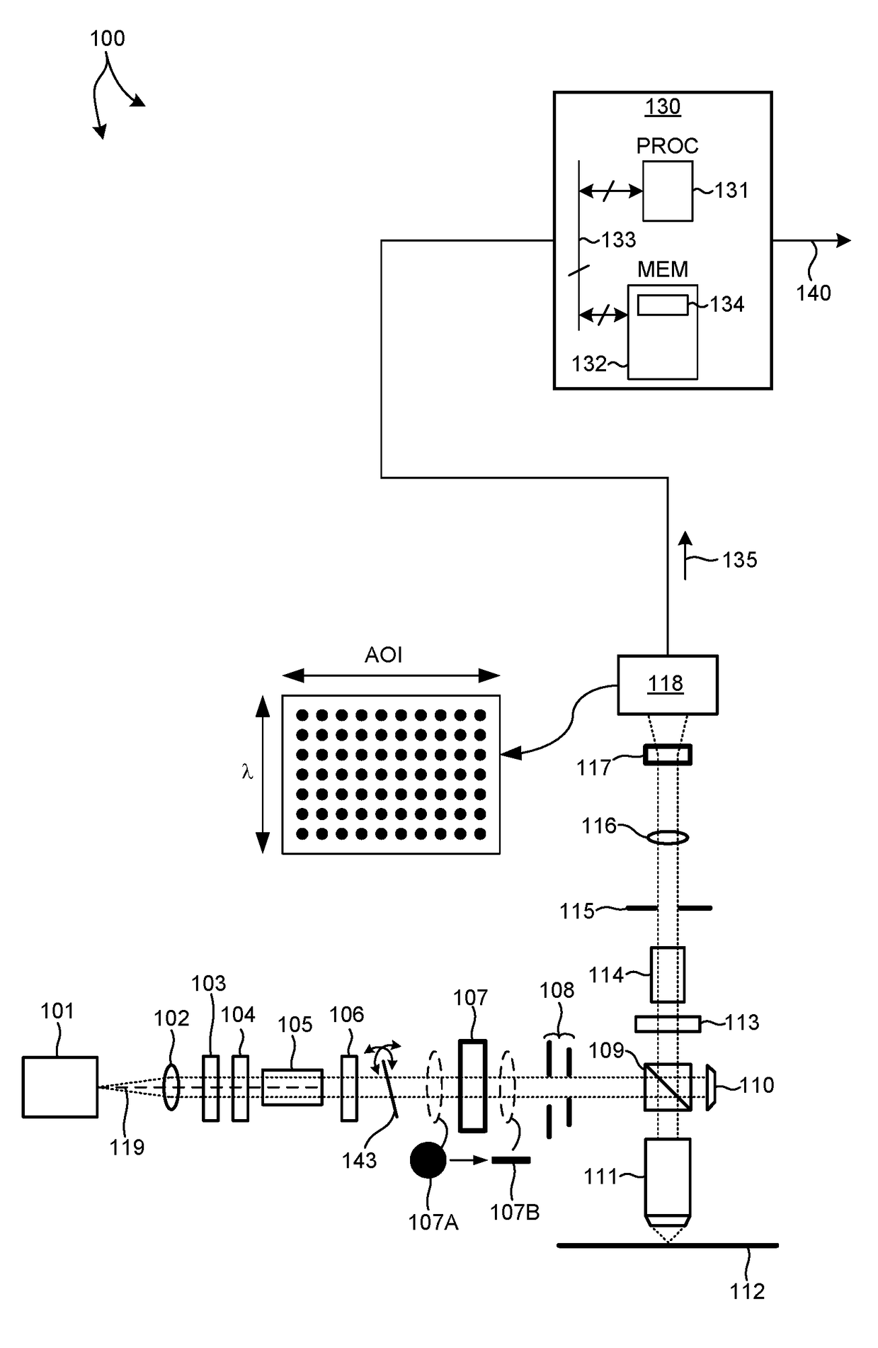
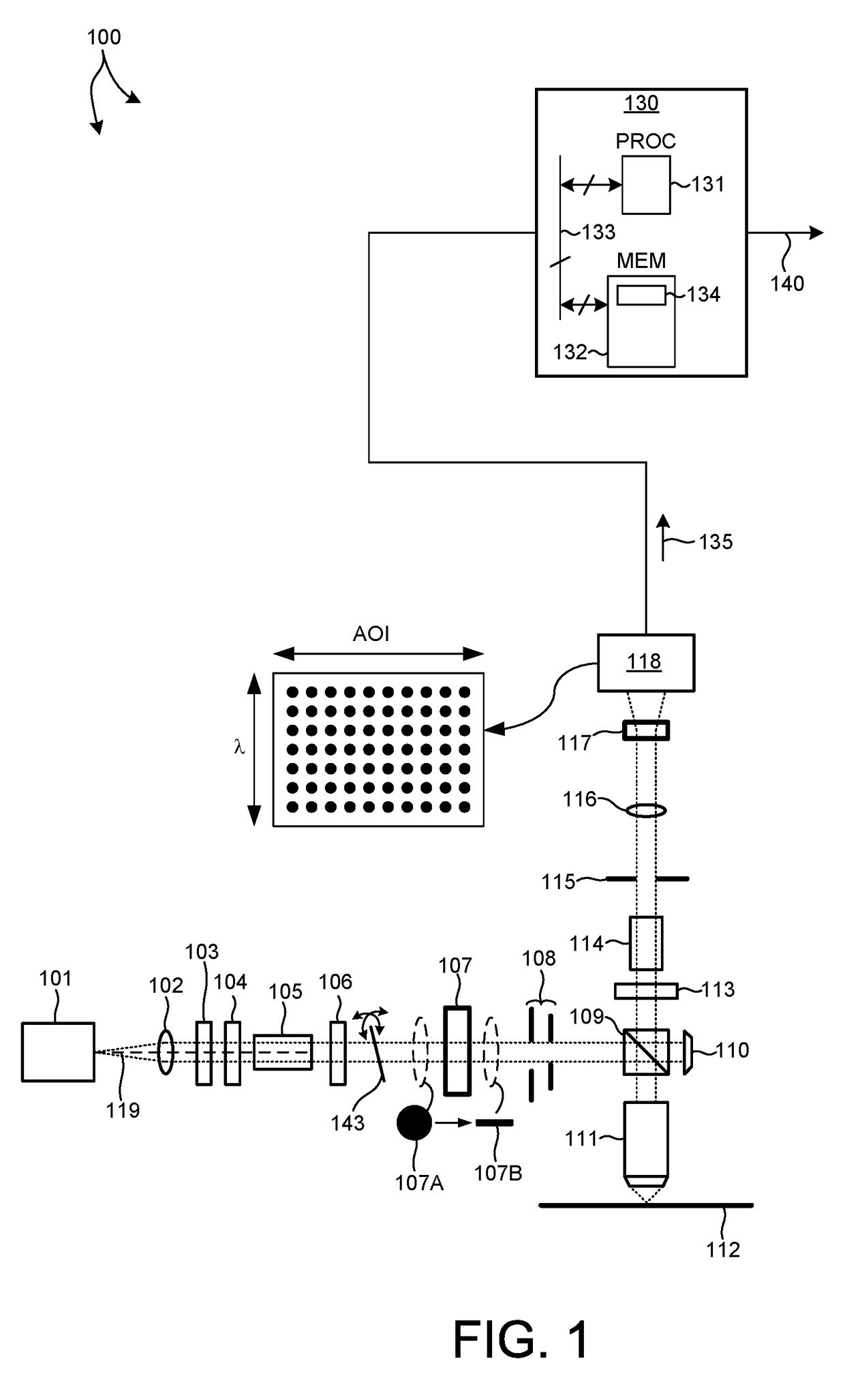
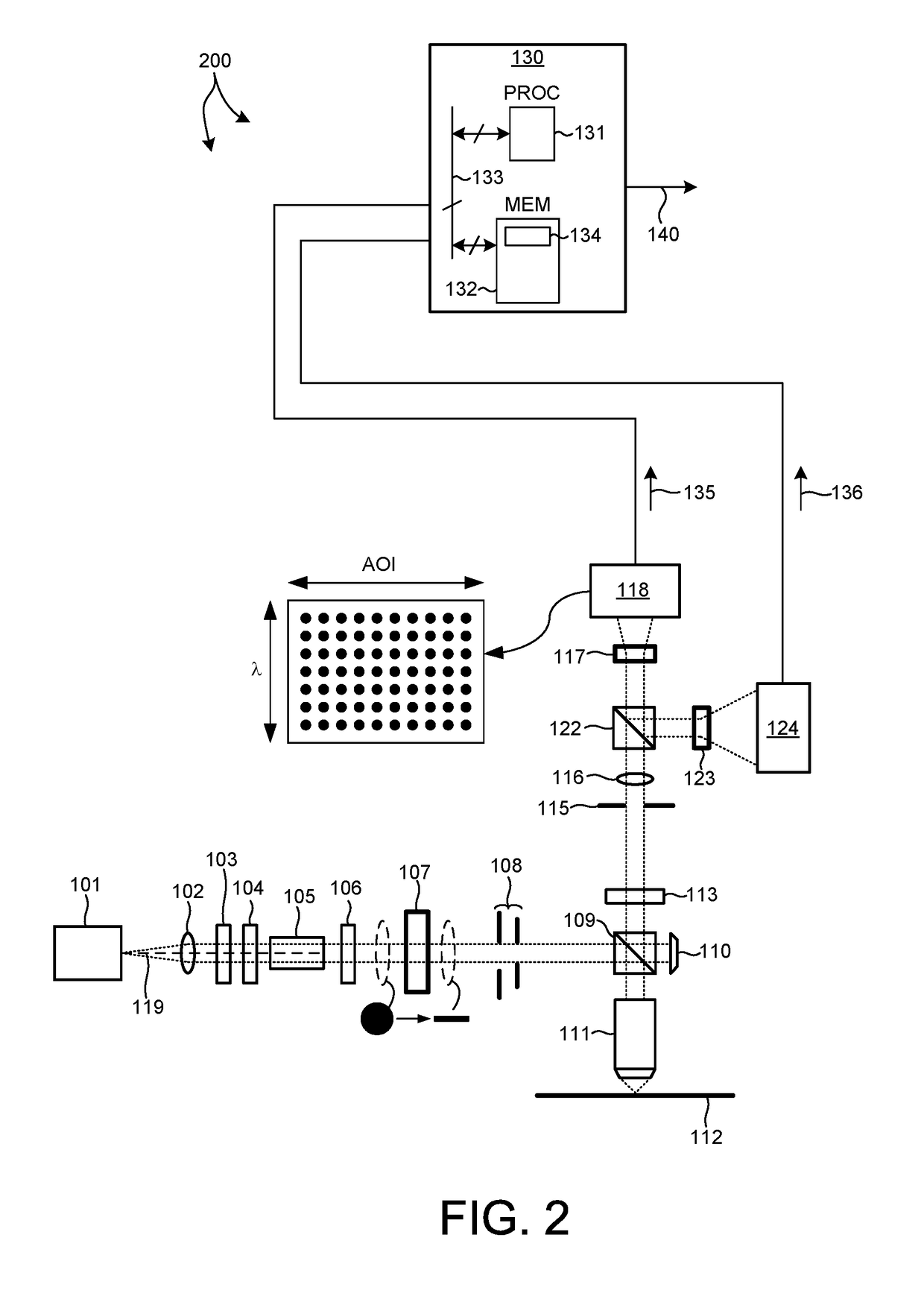
[0058]Methods and systems for overlay measurement with spectroscopic beam profile metrology are presented herein. Several embodiments of a spectroscopic beam profile metrology system are presented herein for illustration purposes. In these embodiments, overlay measurement signals are simultaneously detected over a large wavelength range and a large range of angles of incidence. By simultaneously acquiring overlay signals with large ranges of wavelength and angle of incidence, optimal wavelength and AOI ranges may be identified quickly for each particular measurement application. In addition, one or more broadband illumination sources may be employed to provide illumination over a range of wavelengths, simultaneously.

[0059]Grating measurements are particularly relevant to the measurement of overlay. The objective of ov...


PUM


Abstract

A spectroscopic beam profile metrology system simultaneously detects measurement signals over a large wavelength range and a large range of angles of incidence (AOI). In one aspect, a multiple wavelength illumination beam is reshaped to a narrow line shaped beam of light that is projected onto an overlay metrology target such that the direction of the line shaped beam is aligned with the direction of extent of a grating structure of the overlay metrology target. Collected light is dispersed across a detector according to AOI in one direction and according to wavelength in another direction. The measured signal at each detector pixel is associated with a particular AOI and wavelength. The collected light includes first order diffracted light, zero order diffracted light, or a combination thereof. In some embodiments, first order diffracted light and zero order diffracted light are detected over separate areas of the detector.

Description

CROSS REFERENCE TO RELATED APPLICATION[0001]The present application for patent claims priority under 35 U.S.C. §119 from U.S. provisional patent application Ser. No. 62 / 222,314, entitled “Spectroscopic BPR Method and Apparatus for Overlay Measurement,” filed Sep. 23, 2015, the subject matter of which is incorporated herein by reference in its entirety.TECHNICAL FIELD[0002]The described embodiments relate to metrology systems and methods, and more particularly to methods and systems for improved measurement of parameters characterizing semiconductor manufacturing processes and structures generated by semiconductor manufacturing processes.BACKGROUND INFORMATION[0003]Semiconductor devices such as logic and memory devices are typically fabricated by a sequence of processing steps applied to a specimen. The various features and multiple structural levels of the semiconductor devices are formed by these processing steps. For example, lithography among others is one semiconductor fabricati...

Claims


Application Information

Patent Timeline
IPC IPC(8): G03F9/00
CPCG03F9/7046G03F9/7065G03F7/70633G03F9/7053G03F9/7049H01L22/12
Inventor FU, JIYOUSAPIENS, NOAMPETERLINZ, KEVIN A.PANDEV, STILIAN IVANOV
Owner KLA TENCOR TECH CORP
Learn More