3D printing device and method

a 3d printing and printing device technology, applied in the field of three-dimensional technology, can solve the problems of not being able to guarantee the accuracy of manufacture, and achieve the effects of improving the molding precision of 3d printing, short light path, and low graphic deformation ra

Inactive Publication Date: 2017-03-16
BOE TECH GRP CO LTD
View PDF1 Cites 13 Cited by
  • Summary
  • Abstract
  • Description
  • Claims
  • Application Information

AI Technical Summary

Benefits of technology

[0020]With the liquid crystal display screen and the light source system that provides light to the liquid crystal display screen acting as a curing equipment of the 3D printing device, the curing equipment in the 3D printing device is improved, and the improved curing equipment has a short light path, and a low graphic deformation rate, so the molding precision of 3D printing is significantly improved.

Problems solved by technology

However, in an actual process, the projector's light path is rather long, its light passing through many imaging lens will produce an image that has optical distortions, so cannot guarantee the accuracy of manufacture.

Method used


Image

  • 3D printing device and method
  • 3D printing device and method
  • 3D printing device and method

Examples


Embodiment Construction

[0027]In order to make the objectives, technical solutions and advantages of the embodiments more clear, the embodiments are further described in details in combination with the drawings.

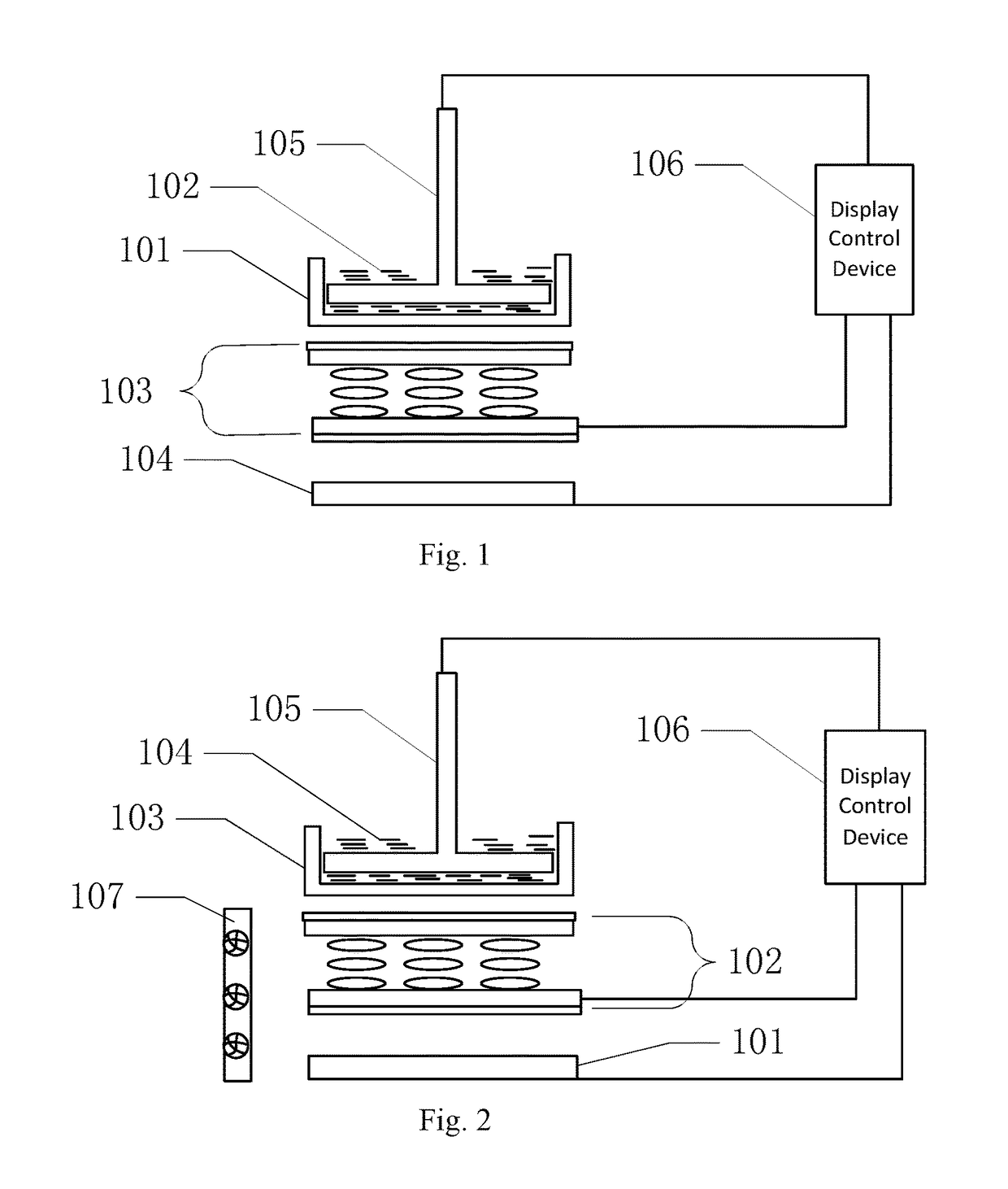
[0028]FIG. 1 is a schematic diagram of the structure of a 3D printing device provided by an embodiment. As shown in FIG. 1, the device comprises: a liquid storage tank 101 with a transparent tank bottom, a liquid crystal display screen 103, a light source system 104, a lifter pallet 105 and a display control device 106.

[0029]The liquid storage tank 101 with a transparent tank bottom is used for holding a liquid photo polymerizable material 102. The liquid crystal display screen 103 is disposed beneath the liquid storage tank 101. The light source system 104 is disposed beneath the liquid crystal display screen 103. The light from the light source system 104 transmits through the liquid crystal display screen 103 and the underside of the liquid storage tank 101 to the liquid photo polymerizable mater...


PUM

PropertyMeasurementUnit
wavelengthaaaaaaaaaa
temperatureaaaaaaaaaa

Abstract

The disclosure relates to a 3D printing device and printing method. The 3D printing device comprises: a liquid storage tank for holding a liquid photo polymerizable material; a liquid crystal display screen; a light source system, the light from the light source system transmits through the liquid crystal display screen to the liquid photo polymerizable material; a lifter pallet disposed in the liquid storage tank, the lower surface of the lifter pallet and the bottom of the liquid storage tank form a cavity, the liquid photo polymerizable material flows into the cavity along with the upward movement of the lifter pallet; a display control device for driving the liquid crystal display screen, the light source system and the lifter pallet respectively. The curing equipment in the 3D printing device has a short light path and a low graphic deformation rate, thus significantly improves the molding precision of 3D printing.

Description

RELATED APPLICATIONS[0001]The present application is the U.S. national phase entry of PCT / CN2015 / 087682 with an International filing date of Aug. 20, 2015, which claims the benefit of Chinese Application No. 201510201691.6, filed on Apr. 24, 2015, the entire disclosures of which are incorporated herein by reference.TECHNICAL FIELD[0002]The disclosure relates to the field of three-dimensional technology, and in particular, to a 3D printing device and method.BACKGROUND ART[0003]With the development of three-dimensional technology, 3D (three dimensional) printing technology is also developing rapidly. The existing 3D printing technology is divided basically into three categories: hot melt plastic base technology, laser sintering molding technology and light curing liquid resin selective area curing molding technology.[0004]In general, the light curing liquid resin selective area curing molding technology uses a projector as the curing device. However, in an actual process, the projecto...

Claims


Application Information

Patent Timeline
Patent Type & Authority Applications(United States)
IPC IPC(8): B29C67/00B33Y30/00B33Y50/02B33Y10/00
CPCB29C67/007B29C67/0088B33Y50/02B33Y30/00B33Y10/00B29C64/129B29C64/386
Inventor LI, WENBO
Owner BOE TECH GRP CO LTD
Why Eureka
Try Eureka