Packaging material for electrical storage devices, electrical storage device, and method for producing embossed packaging material

Active Publication Date: 2017-01-26
TOPPAN PRINTING CO LTD
View PDF2 Cites 2 Cited by
  • Summary
  • Abstract
  • Description
  • Claims
  • Application Information

AI Technical Summary

Benefits of technology

The packaging material in this patent makes it easy to create electrical storage devices with deep recesses in the packaging. It has good formability, meaning it can be easily shaped to fit the device. This improves the performance of the device and makes it easier to produce.

Problems solved by technology

However, pinholes or breaking readily occurs during forming in the packaging material as the formed recess becomes deeper, leading to more deterioration in formability.

Method used


Image

  • Packaging material for electrical storage devices, electrical storage device, and method for producing embossed packaging material
  • Packaging material for electrical storage devices, electrical storage device, and method for producing embossed packaging material
  • Packaging material for electrical storage devices, electrical storage device, and method for producing embossed packaging material

Examples


example 1-1

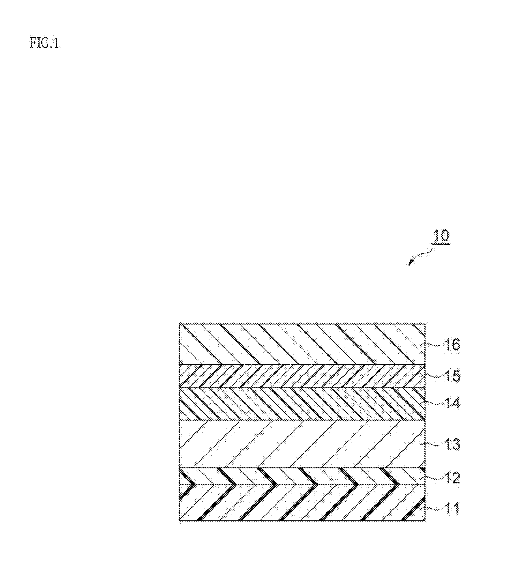
[0145]The treatment agent D-1 was coated on one surface of the metal foil C-1, followed by drying to form the corrosion prevention treatment layer 14 on the metal foil layer 13. Next, the base A-1 was bonded to a surface of the metal foil layer 13 opposite to the surface on which the corrosion prevention treatment layer 14 was formed, by a dry lamination method using the adhesive B-1, so that the thickness of the adhesive layer 12 after lamination was 5 μm, followed by laminating the base layer 11 on the metal foil layer 13 via the adhesive layer 12. The obtained laminate was aged at 60° C. for 6 days. Next, the adhesive layer 15 was formed on the corrosion prevention treatment layer 14 side of the aged laminate by extruding the adhesive resin E-1 with an extruder so that the thickness after and forming the adhesive layer was 20 μm, followed by bonding the Film F-1 on the corrosion prevention treatment layer 14 via the adhesive layer 15 for sandwich lamination, thereby forming the s...

examples 1-2 to 1-16

and Comparative Examples 1-1 to 1-8

[0146]Except for changing the materials used and the thickness of the layer as indicated in Table 1 to form the base layer 11, the adhesive layer 12, the metal foil layer 13, the corrosion prevention treatment layer 14, the adhesive layer 15 and the sealant layer 16, the packaging materials 10 of Examples 1-2 to 1-16 and Comparative Examples 1-1 to 1-8 were prepared in the same manner as Example 1-1. The coefficient of static friction, the difference (μS−μD) between the coefficient of static friction μS and the coefficient of dynamic friction μD, and the tensile elongation of the obtained packaging material 10 are shown together in Table 2. The details of the lubricants (2)-(3) in Table 1 are as follows.

[0147]Lubricant solution (2): 0.5 mass % aliphatic amide lubricant solution

[0148]Lubricant solution (3): 0.1 mass % aliphatic amide lubricant solution

[0149][Evaluation of the Insulating Property]

[0150]The packaging materials 10 obtained in Examples ...

examples 2-1

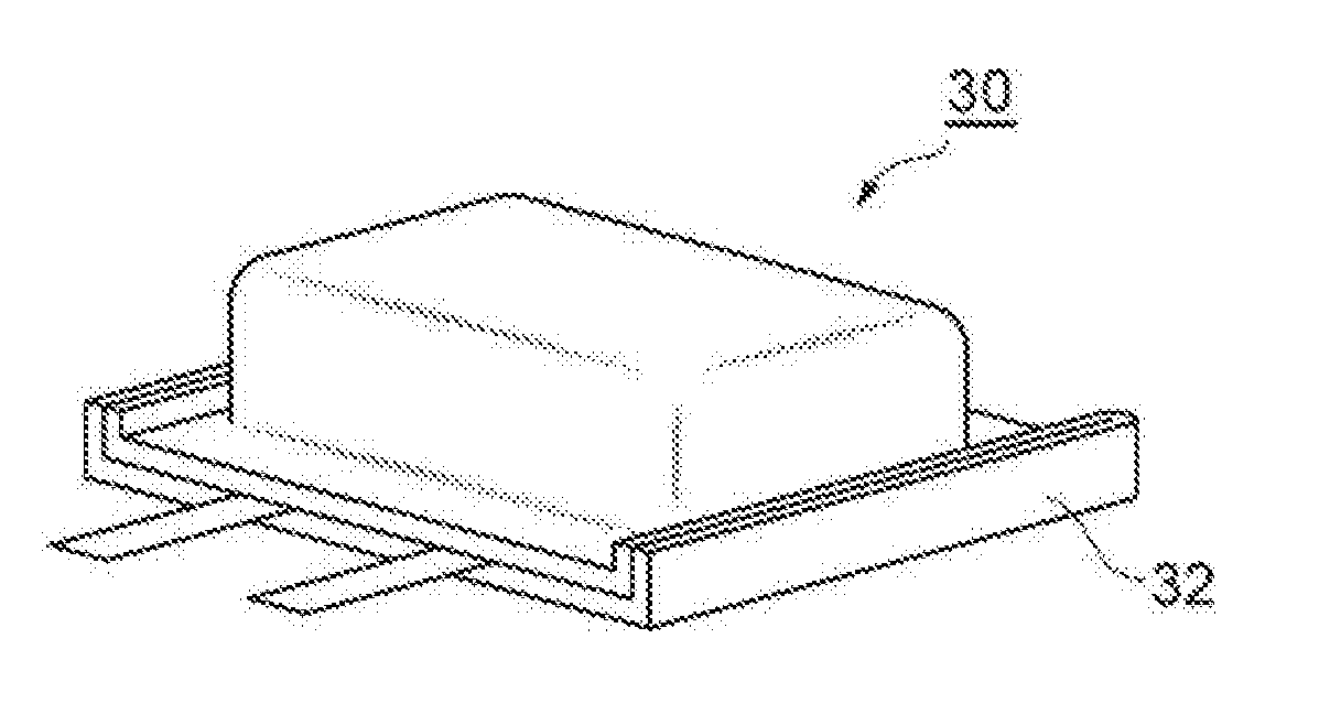
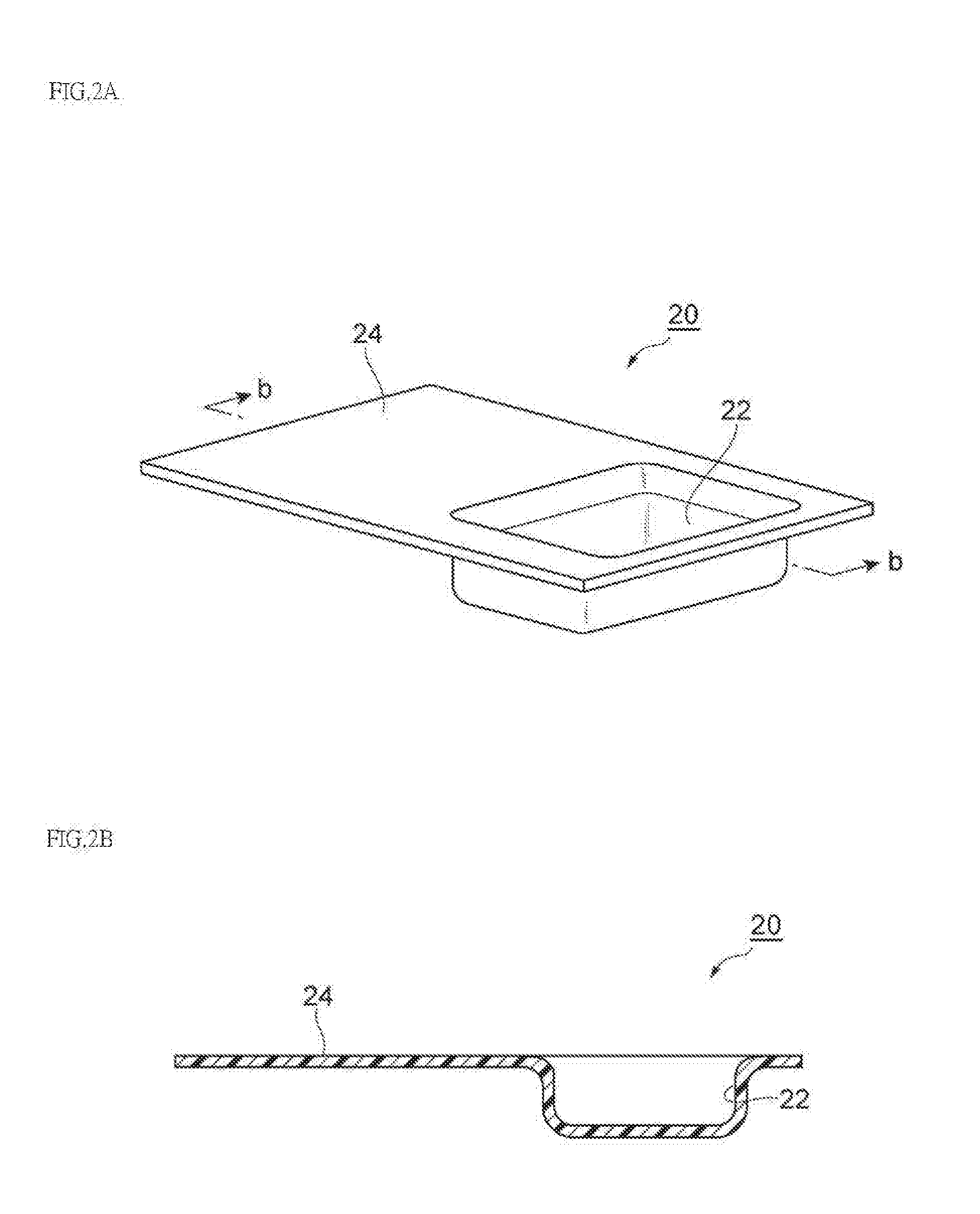
[0182]The packaging material 10 obtained in Example 1-1 was cut to a 210 mm×300 mm blank form, and arranged between the die 27 and the punching die 26 of the forming apparatus 25 which was set to the formed area G-1, the die H-1, the punching die I-1 and the die clearance J-1, so that the sealant layer 16 was the upper surface. Then, the packaging material 10 was fixed on the die 27 with the film presser 23 and the packaging material 10 was pressed by the punching die 26 to a predetermined depth and cold formed under the conditions of 23° C. and 50% RH to obtain the embossed packaging material 20.


PUM

PropertyMeasurementUnit
Fractionaaaaaaaaaa
Percent by massaaaaaaaaaa

Abstract

A packaging material for electrical storage devices which includes a base layer, a metal foil layer arranged on the base layer, and a sealant layer arranged on the metal foil layer. In the packaging material for electrical storage devices, the base layer includes at least one of a stretched polyester resin and a stretched polyamide resin, and the metal foil layer is an aluminum foil containing iron in the range of about 0.5 mass % or more to about 5.0 mass % or less. The packaging material has a tensile elongation of about 50% or more both the MD and TD directions of the base layer.

Description

CROSS-REFERENCE TO RELATED PATENT APPLICATIONS[0001]This application is a continuation application filed under 35 U.S.C. §111(a) claiming the benefit under 35 U.S.C. §§120 and 365(c) of International Application No. PCT / JP2015 / 061008 filed on Apr. 8, 2015, which is based upon and claims the benefit of priority of Japanese Patent Application No. 2014-080363, filed on Apr. 9, 2014, the entireties of which are hereby incorporated by reference.TECHNICAL FIELD[0002]The present invention relates to a packaging material for electrical storage devices, an electrical storage device, and a method for producing an embossed packaging material.BACKGROUND[0003]As electrical storage devices, for example, secondary batteries such as lithium ion batteries, nickel hydrogen batteries, or lead storage batteries, or electric double layer capacitors are known. The further downsizing of electrical storage devices is sought because of the downsizing of mobile devices, limitations of installation spaces, et...

Claims


Application Information

Patent Timeline
IPC IPC(8): H01M2/02H01M10/058H01M2/06H01M10/0525H01M50/105H01M50/119H01M50/121H01M50/129H01M50/133H01M50/136H01M50/141H01M50/178
CPCH01M2/0287H01M2/028H01M2/0285H01M2002/0297H01M10/058H01M2/06H01M10/0525Y02E60/10Y02P70/50H01M50/133H01M50/105H01M50/141H01M50/121H01M50/129H01M50/178H01M50/136H01M50/119B32B7/12B32B15/088B32B15/09B32B15/20B32B27/34B32B27/36H01M10/049B32B2457/16H01M50/124Y02E60/13H01M50/131
Inventor TANIGUCHI, TOMOAKI
Owner TOPPAN PRINTING CO LTD
Why Eureka
Try Eureka