
High fatigue strength components requiring areas of high hardness

a technology of fatigue strength and components, applied in the field of high fatigue strength components, can solve the problems of limiting or compromising the fatigue strength of such components, affecting the hardness of the area on each gear tooth, and affecting the hardness of wear-resistant components, etc., and achieves the effect of high fatigue strength and high hardness for wear

Active Publication Date: 2016-10-13
METAL IMPROVEMENT
View PDF2 Cites 15 Cited by
  • Summary
  • Abstract
  • Description
  • Claims
  • Application Information

AI Technical Summary

Benefits of technology

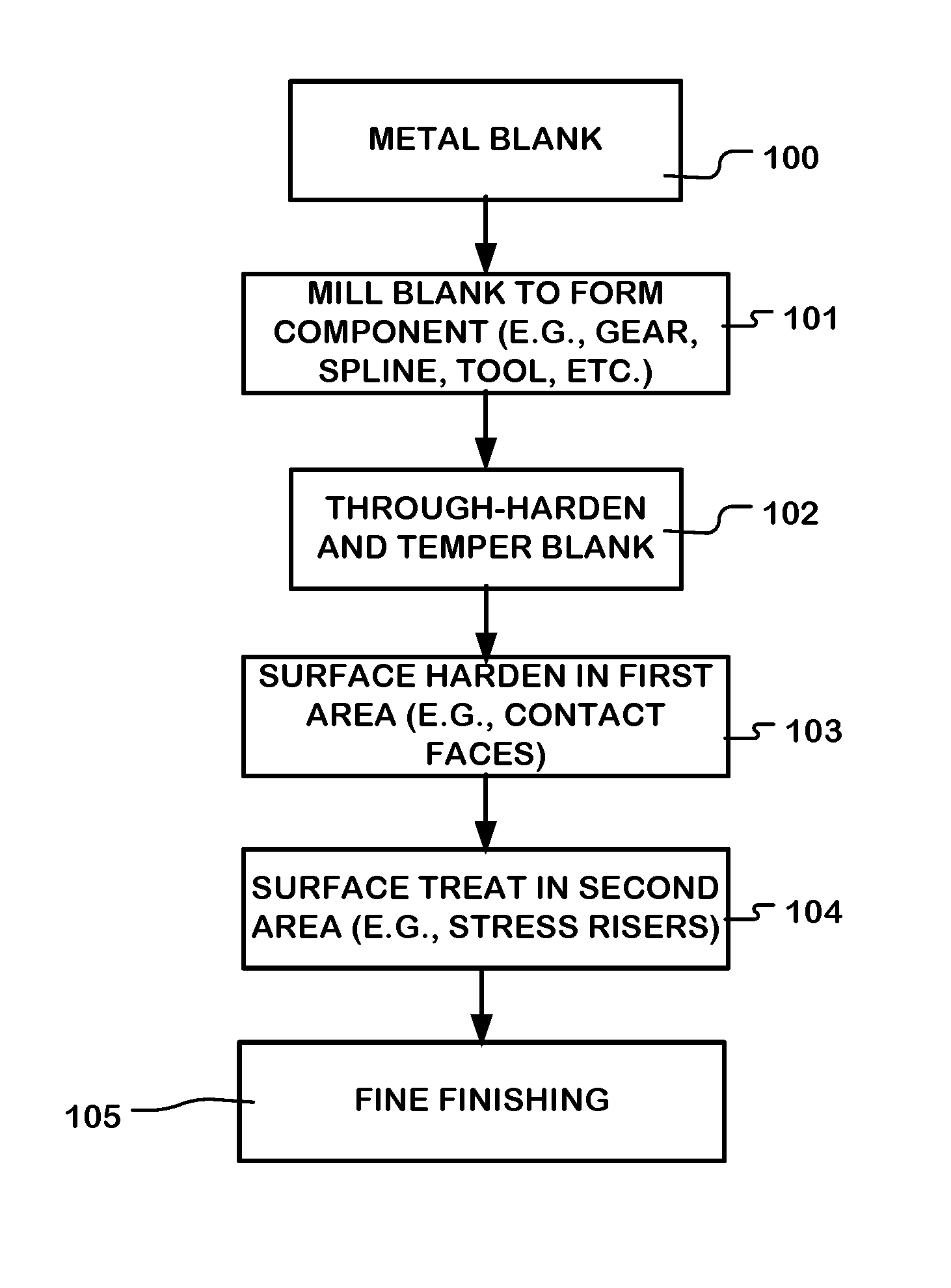
This patent describes a way to make metal components that have very high hardness in areas that are in contact with other materials, and also have high fatigue strength in areas that carry bending, axial, or torsional loads. The methods involve applying a hardening treatment to a first surface layer of the component, such as carburizing or nitriding, in the first area that is subject to heavy wear. Then, a different surface treatment is applied in the second area that is subject to high bending or torsion loading. This second treatment induces compressive stress without reducing fracture toughness, which means it increases the hardness of the material without making it weaker or more likely to break. This results in components that can have both high hardness and high fatigue strength.

Problems solved by technology

Some metal components have contact surfaces that are subject to wear.
However, surface hardening treatments can limit or compromise the fatigue strength of such components.
However, this area on each gear tooth receives tensile loading due to the bending moment created during the driving of the gear.
One problem with selective hardening of the contact faces arises because selective hardening can result in somewhat lower fatigue strength in areas not subject to the hardening process.
Although these surface hardening treatments like carburization add yield strength and compressive stress, the additional hardening significantly reduces the ductility and thus the fracture toughness and corresponding fatigue strength.
This reduction of fatigue strength is undesired in the areas that flex or torque.
However, generating compressive stress by carburization increases the material hardness.
Above certain levels this increased hardness reduces ductility and thus fracture toughness.
The loss in ductility as the hardness is increased reduces the fracture toughness and thus reduces the fatigue strength.

Method used


Image

  • High fatigue strength components requiring areas of high hardness
  • High fatigue strength components requiring areas of high hardness
  • High fatigue strength components requiring areas of high hardness

Examples


Embodiment Construction

[0026]A detailed description of embodiments of the technology is provided with reference to the FIGS. 1-7.

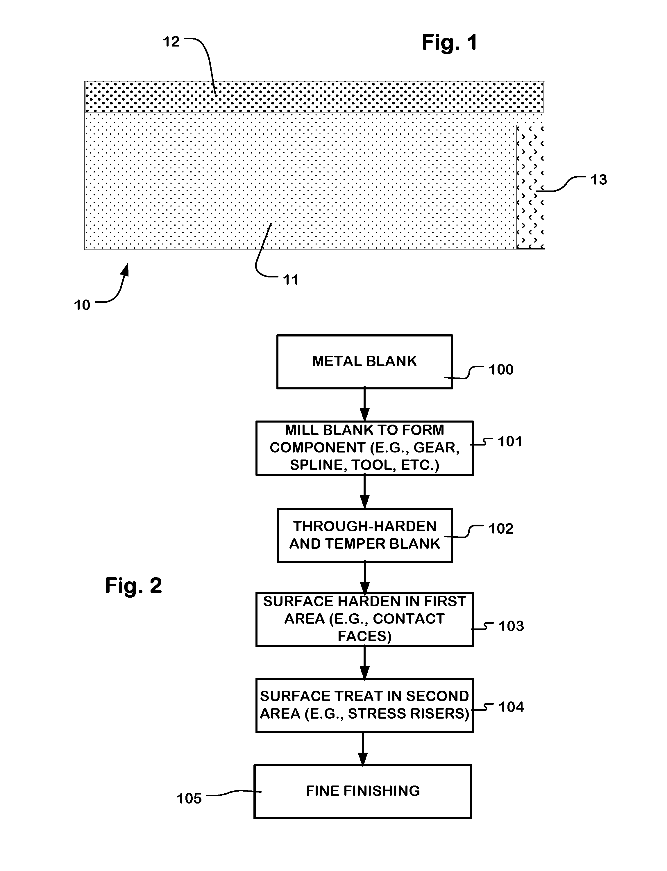
[0027]FIG. 1 is a simplified diagram of a metal component 10 including a component core 11 which comprises a metal, such as steel, titanium and titanium alloys, aluminum and aluminum alloys, nickel based alloys and so on. The material of the core 11 can be brought to a desired level of hardness as discussed below. The component 10 has a surface hardened, first surface layer 12 in a first area on the surface of the component, and a surface compressive-stress treated, second surface layer 13 in a second area. The second surface layer has residual compressive stress different than the first surface layer, and has hardness different than the first surface layer.

[0028]The component 10 in some embodiments can have a relatively hard core material such as tool steel, which can be made relatively hard. Tool steel is a variety of carbon and alloy steels well-suited to be made into tools. ...


PUM

PropertyMeasurementUnit
fatigue strengthaaaaaaaaaa
tensile strengthaaaaaaaaaa

Abstract

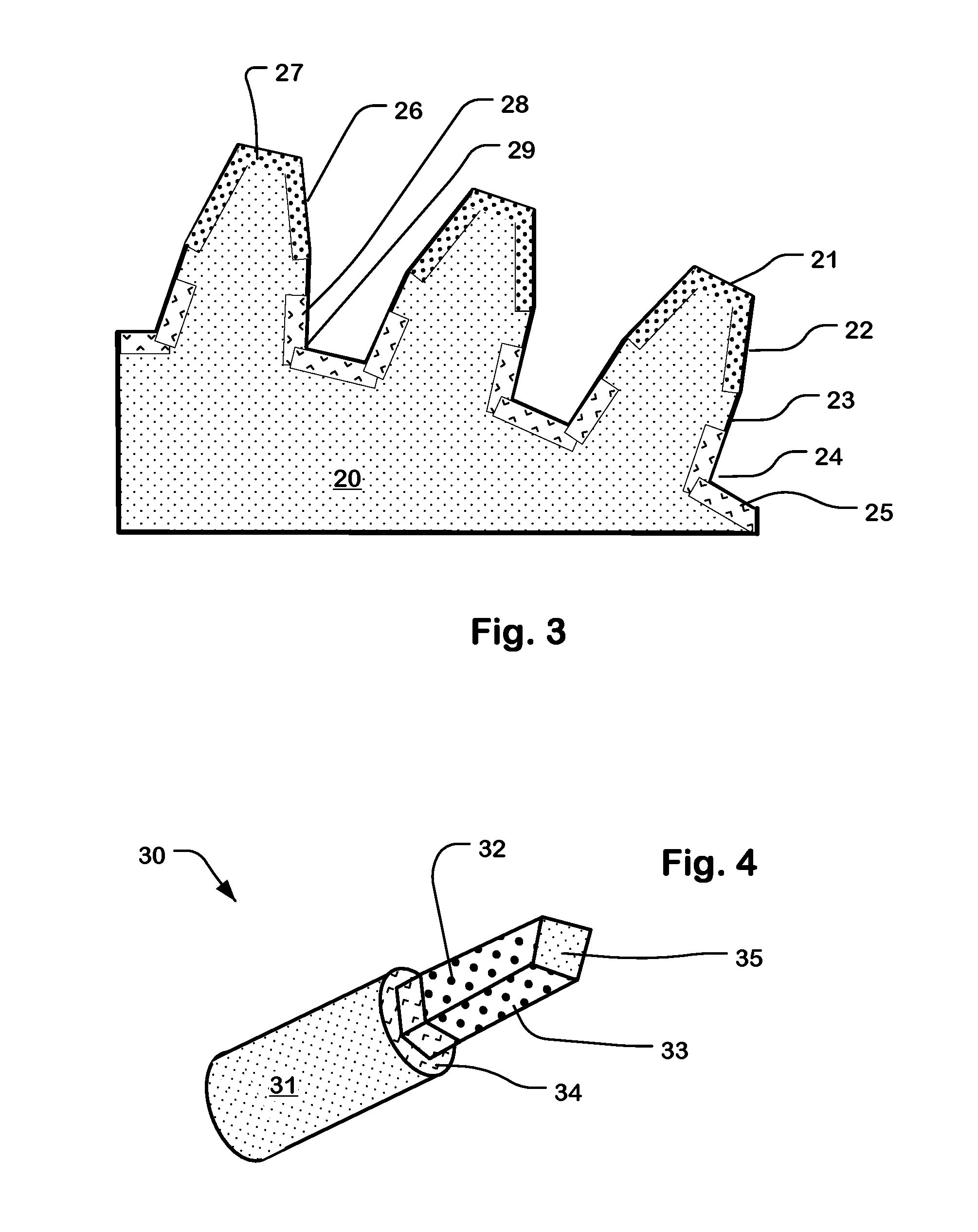
Metal components subject to wear or contact fatigue in a first area, and subject to bending, axial and / or torsional stress loading in a second area comprise a surface hardened, first surface layer in the first area; and a surface compressive-stress treated, second surface layer in the second area. The second surface layer has a material hardness different from, and typically lower than the first surface layer, and induced residual compressive stress to improve fatigue strength. Example components described include a gear, a cog, a pinion, a rack, a splined shaft, a splined coupling, a torqueing tool and a nut driving tool. A hybrid manufacturing process is described, including area-selective surface hardening combined with a process to add compressive stress to fatigue failure prone areas.

Description

[0001]Benefit of U.S. Provisional Patent Application No. 62 / 144,776, filed 8 Apr. 2015 is hereby claimedBACKGROUND[0002]1. Technological Field[0003]The present technology relates to high fatigue strength components requiring areas of high hardness, and to methods of manufacturing such components.[0004]2. Description of Related Art[0005]Some metal components have contact surfaces that are subject to wear. In some components, the contact surfaces of the components are subjected to a surface hardening treatment to improve wear resistance. However, surface hardening treatments can limit or compromise the fatigue strength of such components.[0006]For example, gears have contact faces that can be subjected to surface hardening techniques. See Shigley, “Mechanical Engineering Design”, McGraw-Hill Book Company 1963, p 380, FIG. 11-1. At the root of the tooth, the transition geometry from the tooth to the base of the gear called the root radius (or fillet radius in Shigley), results during m...

Claims


Application Information

Patent Timeline
Patent Type & Authority Applications(United States)
IPC IPC(8): C21D1/18C23C8/26C23C8/80C21D9/32C21D9/30C21D1/10C21D9/28C21D7/06C21D7/08C21D10/00C21D1/42C23C8/22C21D9/00
CPCC21D1/18C23C8/22C23C8/26C23C8/80C21D9/32C21D9/30C21D1/10C21D9/28C21D7/06C21D7/08C21D10/005C21D1/42C21D9/0068C23C8/04C23C8/32Y02P10/25B33Y40/20B22F10/62B22F10/64B22F5/08B22F2003/241
Inventor HACKEL, LLOYD A.
Owner METAL IMPROVEMENT
Learn More