
Wavelength selective heat radiation material selectively radiating heat radiation light corresponding to infrared ray transmission wavelength region of resin member and method for manufacturing the same

Active Publication Date: 2016-09-08
OKITSUMO +1
View PDF0 Cites 4 Cited by
  • Summary
  • Abstract
  • Description
  • Claims
  • Application Information

AI Technical Summary

Benefits of technology

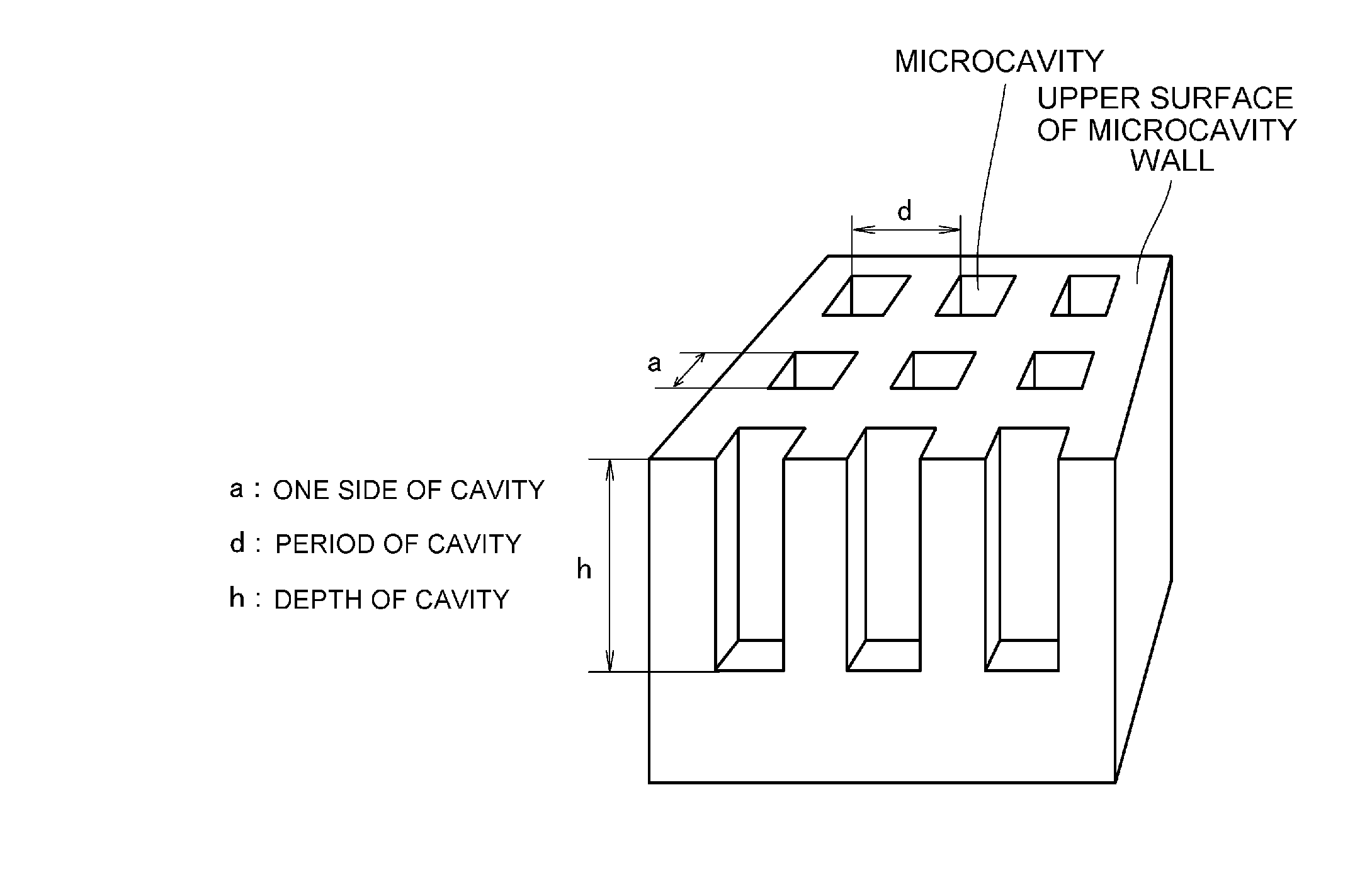
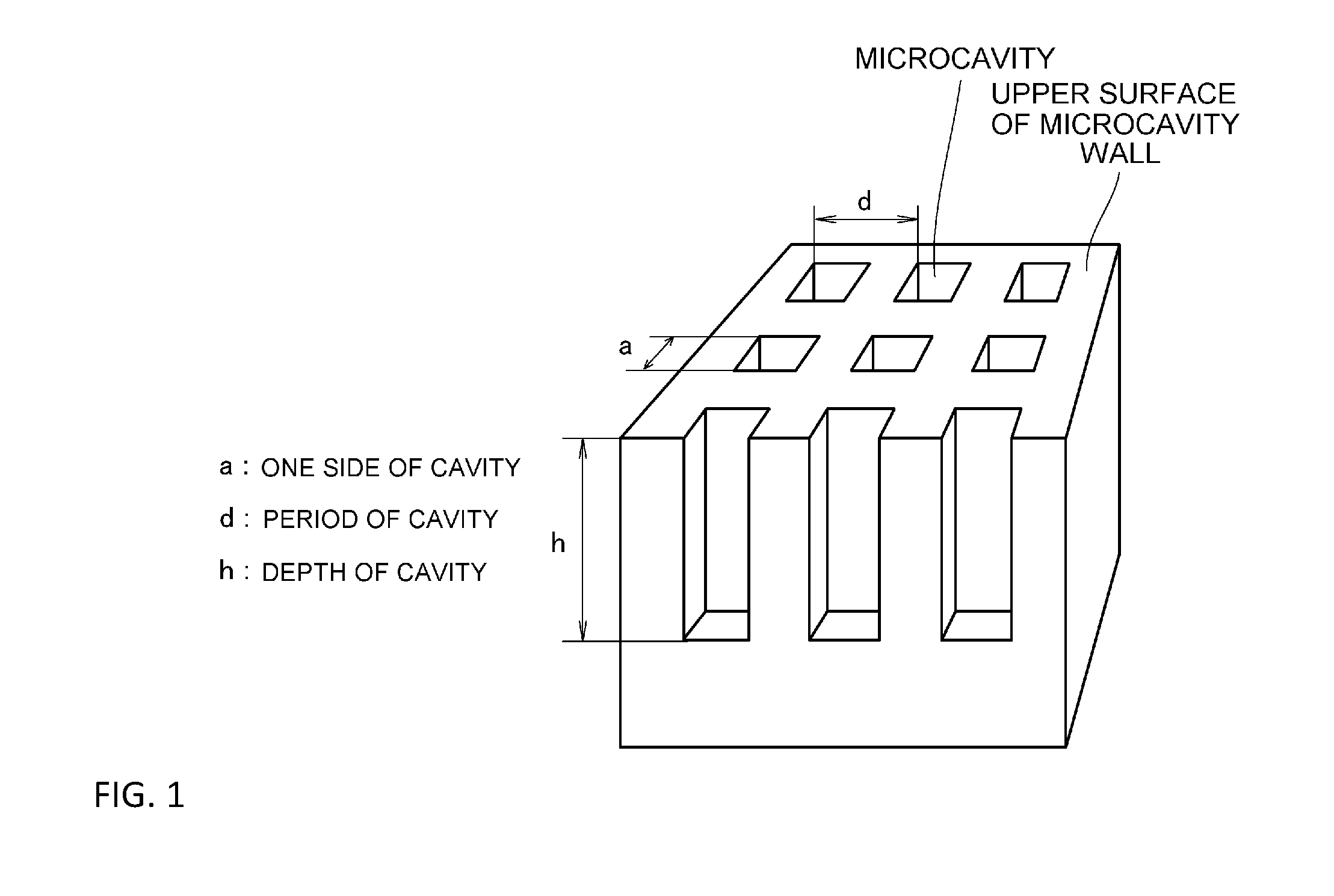
The present invention is for a material that can improve heat radiation from a resin member having infrared ray transmission wavelength region. The material has microcavities with an aspect ratio of 3.3 or more, which results in a high emissivity of 0.85 or more. The method for manufacturing the material includes using a stamp with a semi-cylindrical-shaped pressing surface to prevent air from entering during mask transcription and improve adhesiveness, allowing for more precise etching. Overall, this invention provides an effective solution for enhancing heat radiation efficiency of the resin member.

Problems solved by technology

In addition, since a variety of resin materials are used in an electronic device-related component, due to the characteristic of the resin material that is the inferiority in heat conductivity, heat generated by the electronic device is caught by a cover or the like made of the resin and is accumulated, thereby leading to the problem in that the temperature increase causes a failure rate of the electronic device to be increased and the life of each component to be shortened.
However, in the conventional technology in which the semiconductor photolithography technology and the electrolytic etching method are combined, an upper portion of a cavity wall of each of the obtained microcavities is chipped or thin-walled, thereby leading to a problem in that it is impossible to selectively radiate the heat radiation light corresponding to the infrared ray transmission wavelength region of the resin member at the emissivity as originally designed.
In addition, with respect to the chipping or thin-walling of the upper portion of the cavity wall, there also is a problem in that any finding on what influence to be exerted on the radiation characteristic of the heat radiation light corresponding to the infrared ray transmission wavelength region of the resin member has not been obtained.
This is because if the aspect ratio of each of the microcavities is below 0.8, a disadvantage in that a selective radiant intensity is reduced is caused, and on the other hand, if the aspect ratio is above 3.0, a disadvantage in that the formation of the microcavities is extremely difficult is caused.
However, in the conventional technology in which the semiconductor photolithography technology and the electrolytic etching method are combined or the nanoimprint lithography, there is a problem in that it is difficult to form microcavities each having an aspect ratio larger than 3.0 without roughening the upper portion of the cavity wall.
In addition, there also is a problem in that any finding on what emissivity at which the wavelength selective heat radiation material, if the aspect ratio of each of the microcavities is larger than 3.0, is capable of selectively radiating the heat radiation light corresponding to the infrared ray transmission wavelength region of the resin member has not been obtained.

Method used


Image

  • Wavelength selective heat radiation material selectively radiating heat radiation light corresponding to infrared ray transmission wavelength region of resin member and method for manufacturing the same
  • Wavelength selective heat radiation material selectively radiating heat radiation light corresponding to infrared ray transmission wavelength region of resin member and method for manufacturing the same
  • Wavelength selective heat radiation material selectively radiating heat radiation light corresponding to infrared ray transmission wavelength region of resin member and method for manufacturing the same

Examples


example 1

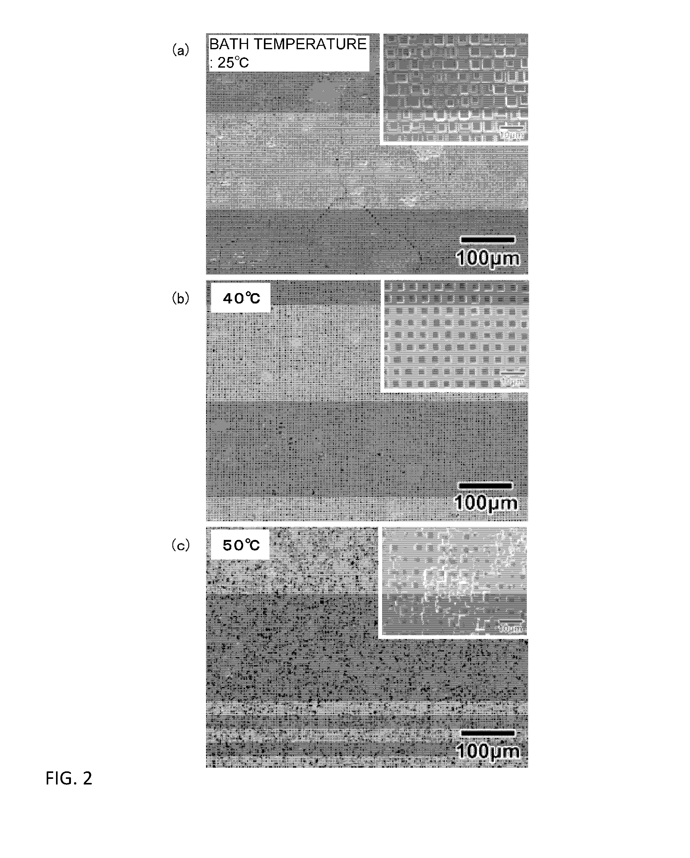
[0070]An aluminum foil whose area occupancy ratio of a (100) crystal plane of a surface was 93% or more was used, said aluminum foil was subjected to electrolytic polishing by using a perchloric acid / ethanol bath, and thereafter, a neoprene thin film layer having a structure in which fine pores each having a size of 2 μm were regularly arrayed at intervals of 5 μm was caused to tightly adhere to the surface thereof for formation. Copper was attached to said aluminum foil by conducting a sputtering process; thereafter, by using an electrolytic bath having a bath temperature of 25° C. and containing a 7M hydrochloric acid aqueous solution, electrolytic etching to the resultant was conducted under the conditions that a current density upon starting electrolysis was 1500 mA / cm2 and after decreasing the current density at a current density decrease rate of 150 mA / cm2 / s up to 200 mA / cm2, the current density of 200 mA / cm2 was retained for 15 seconds. Thereafter, the resultant was immersed ...

example 2

[0071]Under the same conditions as in Example 1, except that the bath temperature of the electrolytic bath was 30° C., electrolytic etching was conducted, thereby obtaining a wavelength selective heat radiation material in which microcavities each having a length a of one side of 3 μm and an opening ratio a / Λ (a: opening size, Λ: opening period) of 0.6 were formed.

example 3

[0072]Under the same conditions as in Example 1, except that the bath temperature of the electrolytic bath was 35° C., electrolytic etching was conducted, thereby obtaining a wavelength selective heat radiation material in which microcavities each having a length a of one side of 3 μm and an opening ratio a / Λ (a: opening size, Λ: opening period) of 0.6 were formed.


PUM

PropertyMeasurementUnit
Temperatureaaaaaaaaaa

Abstract

An object is to provide a method for manufacturing a wavelength selective heat radiation material in which a surface roughness of an upper portion of a cavity wall defining each microcavity is suppressed or in which microcavities each having an aspect ratio larger than 3.0 are formed. For the wavelength selective heat radiation material, a base material having a mask having predetermined openings tightly adhered to a surface thereof, or a base material in which depressions are previously formed on one surface thereof by pressing a die having projections arrayed so as to correspond to positions of microcavities thereagainst, is subjected to anisotropic etching, thereby providing a wavelength selective heat radiation material in which the surface roughness of the upper portion of the cavity wall defining each of the microcavities is suppressed or a wavelength selective heat radiation material having microcavities whose each aspect ratio is larger than 3.0.

Description

TECHNICAL FIELD[0001]The present invention relates to a wavelength selective heat radiation material which selectively radiates heat radiation light corresponding to an infrared ray transmission wavelength region of a resin member and to a method for manufacturing the wavelength selective heat radiation material, and in particular, the present invention relates to a method for manufacturing a wavelength selective heat radiation material which selectively radiates, at a high emissivity, heat radiation light corresponding to an infrared ray transmission wavelength region of a resin member from a heat radiation surface of the wavelength selective heat radiation material toward the resin member, by placing the wavelength selective heat radiation material between a heat generation source and the resin member in an electronic device in which the heat generation source is covered with the resin member having the infrared ray transmission wavelength region.BACKGROUND ART[0002]In recent year...

Claims


Application Information

Patent Timeline
IPC IPC(8): H01L23/367C23C14/34C25F3/14C23C14/04C23C14/58C25F3/22C23C14/20C23C14/00
CPCH01L23/367C23C14/205C23C14/34C23C14/0021C25F3/14C23C14/5886C23C14/5873C23C14/5846C25F3/22C23C14/042C25F3/04C25F3/20H01L23/373H01L2924/0002C23C14/165H01L2924/00C23C14/16C23F1/20H05K7/2039H01L23/36H05K7/20
Inventor MASUDA, HIDEKIKONDO, TOSHIAKITOYONAGA, TAKASHIKIMURA, NAOSHIYOSHIOKA, FUMITAKA
Owner OKITSUMO
Learn More