High-Temperature Superconducting High-Current Devices Compensated for Anisotropic Effects

a high-current device and superconducting technology, applied in the field of electromagnetism, can solve the problems of inherently limited current-carrying capacity of power transmission cables and may not be optimal for prior art use,

Active Publication Date: 2016-08-18
MASSACHUSETTS INST OF TECH
View PDF4 Cites 6 Cited by
  • Summary
  • Abstract
  • Description
  • Claims
  • Application Information

AI Technical Summary

Benefits of technology

[0007]Embodiments of the present invention provide high-temperature superconducting high-current cables. Briefly described, the present invention is directed to a high-temperature superconducting (HTS) cable subassembly having a rectangular shaped cross section. The subassembly includes a stack of HTS tapes formed of a superconducting material, and a cable subassembly wrapper wrapped around the stack of tapes. The tapes in the stack are slidably arranged in a parallel fashion. A cable assembly is formed of a cable assembly wrapper formed of a second non-superconducting material disposed around an n×m array of cable subassemblies. Within a cable assembly, a first cable subassembly of the array of subassemblies is oriented substantially perpendicular to a second cable subassembly with regard to the plurality of tapes. A compound cable assembly is formed by joining two or more cable assemblies. A high-temperature superconducting magnet is formed of a solenoid formed of a cable subassembly, a cable assembly, and / or a compound cable assembly.

Problems solved by technology

However, as noted above, the current-carrying capacity of power transmission cables are inherently limited due to the geometry of their physical configuration, particularly when employed in a solenoidal magnet configuration.
In addition, HTS power transmissions may not be optimal for use in prior art HTS magnets since they are generally not designed to achieve maximum or uniform current density.

Method used


Image

  • High-Temperature Superconducting High-Current Devices Compensated for Anisotropic Effects
  • High-Temperature Superconducting High-Current Devices Compensated for Anisotropic Effects
  • High-Temperature Superconducting High-Current Devices Compensated for Anisotropic Effects

Examples


first embodiment

[0045]The subassembly wrapper 320 is wrapped around the stack of tapes 310, for example, with windings of a wrapper material forming the subassembly wrapper 320 wound in a helical fashion around the cable subassembly 300 for substantially the length of the cable subassembly 300. The subassembly wrapper 320 may be formed of wire or tape wrapping material formed of a conducting material, for example, copper, or a non-conducting or insulating material, for example, stainless steel. In the first embodiment, the subassembly wrapper 320 is not formed of a superconducting material. The windings of the subassembly wrapper 320 may overlap, may abut, or may have a gap between successive windings. Other subassembly wrapper 320 configurations are also possible, for example, a braided wire or tape wrapping. The subassembly wrapper 320 may be relatively thin with respect to the dimensions of the tapes 310, for example, a subassembly wrapper 320 formed of copper on the order of 25 μm thick.

[0046]I...

second embodiment

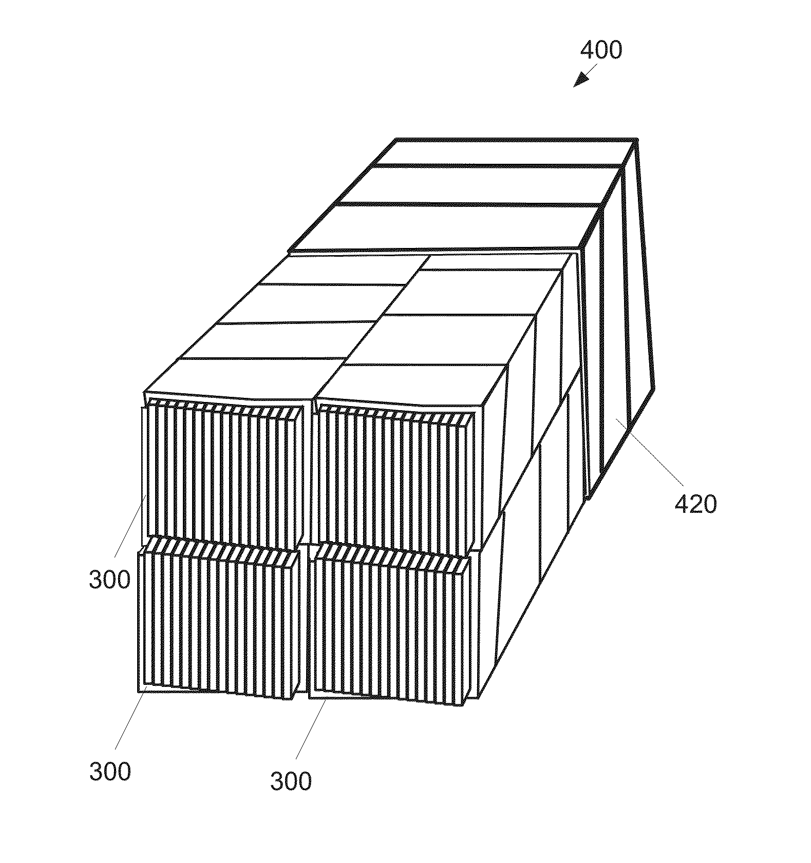
[0053]The cable assembly wrapper 420 may be formed of wire wrapping or tape wrapping material formed of a conducting material, for example, copper, or a non-conducting or insulating material, for example, stainless steel. In the second embodiment, the cable assembly wrapper 420 is not formed of a superconducting material. The windings of the cable assembly wrapper 420 may overlap, may abut, or there may be a gap between successive windings. Other wrapping configurations are also possible, for example, a braided wire wrapping or tape wrapping. The cable assembly wrapper 420 may be relatively thin, for example, a formed of copper on the order of 25-μm thick.

[0054]Under the second embodiment, the cable subassemblies 300 are arranged so that the tapes 310 (FIG. 3) within each of the cable subassemblies 300 within the cable assembly 400 are similarly oriented with respect to one another. In a preferred embodiment, the cable subassemblies 300 in the cable assembly 400 are not soldered tog...

third embodiment

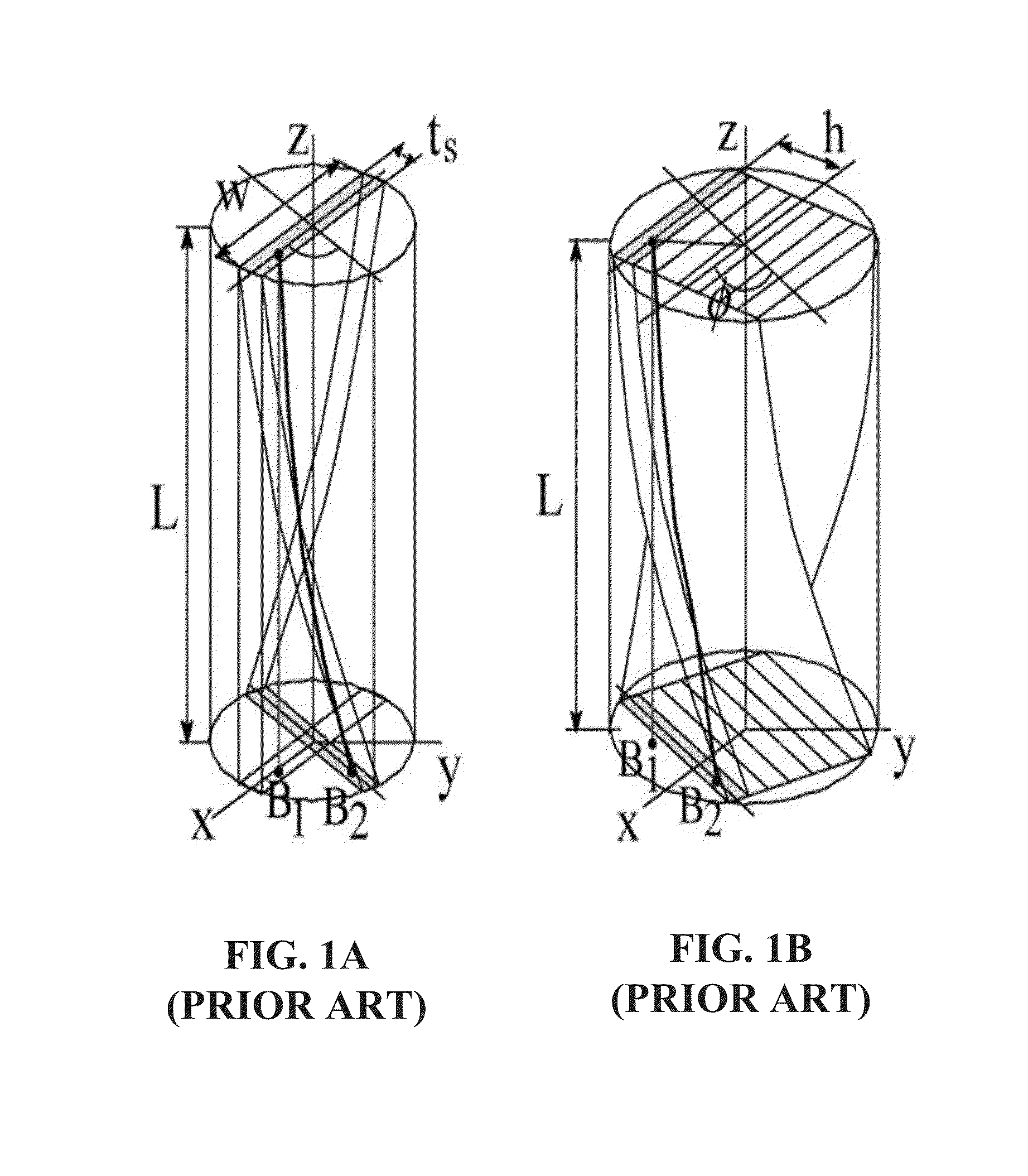
[0059]The superconducting capacity of a cable assembly 400 increases according to the number of subassemblies 300 used in the cable assembly 400. However, the superconducter capacity may not increase proportionally according to the number of subassemblies 300 being used, due to capacity degradation by anisotropy of the magnetic field, particularly when the cable assembly 400 is formed into a solenoid. The anisotropic effect may be mitigated somewhat by using a subassembly 600 according to a HTS-HC, shown in FIGS. 6A-6C. As noted above, the strong magnetic field is substantially parallel to the wide surface of the superconducting tape. The magnetic field impinges upon the superconductor perpendicular to the wide surface, reducing the carrying capacity of the superconductor tape.

[0060]As shown by FIGS. 6A-6C, under the third embodiment, a cable assembly 600 may include multiple cable subassemblies 610, 620 having two distinct orientations with respect to the superconductor tapes. Cabl...


PUM

PropertyMeasurementUnit
widthaaaaaaaaaa
critical currentaaaaaaaaaa
current levelaaaaaaaaaa

Abstract

High-temperature superconducting (HTS) devices and methods are disclosed. An HTS cable subassembly has a rectangular shaped cross section. The subassembly includes a stack of tapes formed of a superconducting material, and a cable subassembly wrapper wrapped around the stack of tapes. The tapes in the stack are slidably arranged in a parallel fashion. A cable assembly is formed of a cable assembly wrapper formed of a second non-superconducting material disposed around an n×m array of cable subassemblies. Within a cable assembly, a first cable subassembly of the array of subassemblies is oriented substantially perpendicular to a second cable subassembly with regard to the plurality of tapes. A compound-cable assembly is formed by joining two or more cable assemblies. A high-temperature superconducting magnet is formed of a solenoidal magnet as well as dipole and quadrupole magnets wound of a cable subassembly, a cable assembly, and/or a compound cable assembly.

Description

CROSS-REFERENCE TO RELATED APPLICATIONS[0001]This application is a continuation-in-part of U.S. patent application Ser. No. 14 / 620,260, filed Feb. 12, 2015, entitled “High-Temperature Superconducting High-Current Cables,” which is incorporated by reference herein in its entirety.FIELD OF THE INVENTION[0002]The present invention relates to electro-magnetics, and more particularly, is related to high temperature superconductors.BACKGROUND OF THE INVENTION[0003]Prior art high-temperature superconductors (HTS), particularly Bi-2223 (Bismuth strontium calcium copper oxide Bi2Sr2Ca2Cu3O10+x) and REBCO (rare-earth barium-copper-oxide) or RE-123 superconductors, are available as a single tape conductor with a maximum width for REBCO of either 10 mm or 12 mm with a critical current at 77 K in self field (s.f.) at the present time of no greater than approximately 500 A.[0004]HTS cables have been developed for applications such as electric power lines, particularly with Bi-2223. Two prior art ...

Claims


Application Information

Patent Timeline
Patent Type & Authority Applications(United States)
IPC IPC(8): H01B12/08H01F41/04H01B13/26H01F6/06
CPCH01B12/08H01B13/26H01F41/048H01F6/06H02G15/34Y02E40/60H10N60/203H10N60/0268
Inventor IWASA, YUKIKAZUBASCUNAN, JUANHAHN, SEUNGYONG
Owner MASSACHUSETTS INST OF TECH
Why Eureka
Try Eureka