
Method for manufacturing optical member, and optical member, transparent member for forming optical member, optical waveguide and optical module

Inactive Publication Date: 2016-07-21
HITACHI CHEM CO LTD
View PDF3 Cites 1 Cited by
  • Summary
  • Abstract
  • Description
  • Claims
  • Application Information

AI Technical Summary

Benefits of technology

The present invention provides a method for manufacturing an optical member and an optical waveguide that have excellent mass productivity and can control the refractive index accurately. The method is suitable for manufacturing an optical waveguide with low optical propagation loss. The technical effects of the invention are improved manufacturing efficiency and accuracy of optical waveguides.

Problems solved by technology

However, to make an antireflection member by above-stated dry deposition method needs processing the member under vacuum.
Therefore, this requirement brings a low productivity problem and further brings anxiety about that exposure to vacuum may damage a transparent member.
Moreover, there was a fear of a positional variation of the distribution of the refractive index when a film has a bent shape (including a bend occurred during manufacturing process), a complicated shape, or an intricate shape.
In addition, in a case where the core pattern of an optical waveguide is formed by etching like Patent Literature 1 describes, it was anxiety that degradation of the optical loss of the light propagating in the core pattern would occur due to some disturbance such as interfacial roughness between the clad and the core pattern, and irregularity of refractive index in the core pattern attributable to the etchant.

Method used


Image

  • Method for manufacturing optical member, and optical member, transparent member for forming optical member, optical waveguide and optical module
  • Method for manufacturing optical member, and optical member, transparent member for forming optical member, optical waveguide and optical module
  • Method for manufacturing optical member, and optical member, transparent member for forming optical member, optical waveguide and optical module

Examples


embodiment 1

Preparation of Resin Film for Forming Transparent Member

[0177][Preparation of Base Polymer: (Meth)acrylic Polymer (P-1) for forming Transparent Member]

[0178]42 parts by weight of propylene glycol monomethyl ether acetate and 21 parts by weight of methyl lactate were weighed and put in a flask equipped with a stirrer, a cooling tube, a gas-introduction tube, a dripping funnel, and a thermometer; then they were stirred while introducing nitrogen gas. The temperature of the liquid was risen to 65° C. and then a mix was dripped over a period of three hours.

[0179]The mix dripped was a blend of 14.5 parts by weight of N-cyclohexyl maleimide, 20 parts by weight of benzyl acrylate, 1.5 parts by weight of o-phenylphenol, 39 parts by weight of acrylate, 14 parts by weight of 2-hydroxyethyl methacrylate, 12.5 parts by weight of methacrylic acid, 4 parts by weight of 2,2′-azobis(2,4-dimethyl valeronitrile), 37 parts by weight of propylene glycol monoethyl ether acetate, and 21 parts by weight o...

embodiment 2

[0194]Another optical member was manufactured in the same manner employed in the embodiment 1, except that the 1.0 wt-% of sodium carbonate aqueous solution was used in place of 1.0 wt-% of potassium carbonate aqueous solution in the embodiment 1.

[0195]The refractive index at the wavelength 830 nm of the supporting film side (the side immersed in the sodium carbonate aqueous solution) of this optical member was measured using a prism-coupled refractometer (Model 2020, by Metricon Co.) The measured refractive index was 1.556. The refractive index was further measured at arbitrary chosen 20 places (the separations between each adjacent places were about one centimeter). The measured refractive indices showed no position-dependent variations. The IR measuring was conducted about the surface; carboxylic anion peak was observed. The EDX measuring was also conducted; sodium was detected. The refraction index of the protection film side (the side not immersed in the sodium carbonate aqueou...

embodiment 3

Preparation of Resin Film for Forming Clad Layer

[Preparation of Base Polymer (A): (Meth)Acrylate Polymer (A-1)]

[0197]46 parts by weight of propylene glycol monomethyl ether acetate and 23 parts by weight of methyl lactate were weighed and put in a flask equipped with a stirrer, a cooling tube, a gas-introduction tube, a dripping funnel, and a thermometer; then they were stirred while introducing nitrogen gas. The temperature of the liquid was risen to 65° C. and then a mix was dripped over a period of three hours.

[0198]The mix dripped was a blend of 47 parts by weight of methyl methacrylate, 33 parts by weight of butyl acrylate, 16 parts by weight of 2-hydroxyethyl methacrylate, 14 parts by weight of methacrylic acid, 3 parts by weight of 2,2′-azobis(2,4-dimethyl valeronitrile), 46 parts by weight of propylene glycol monomethyl ether acetate, and 23 parts by weight of methyl lactate.

[0199]After the three hours of dripping, it was stirred for three hours at 65° C. The stirring was fu...


PUM

PropertyMeasurementUnit
Transparencyaaaaaaaaaa
Circumferenceaaaaaaaaaa
Distributionaaaaaaaaaa

Abstract

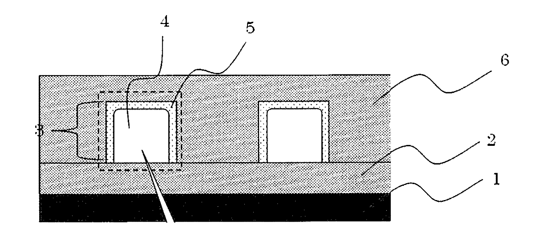
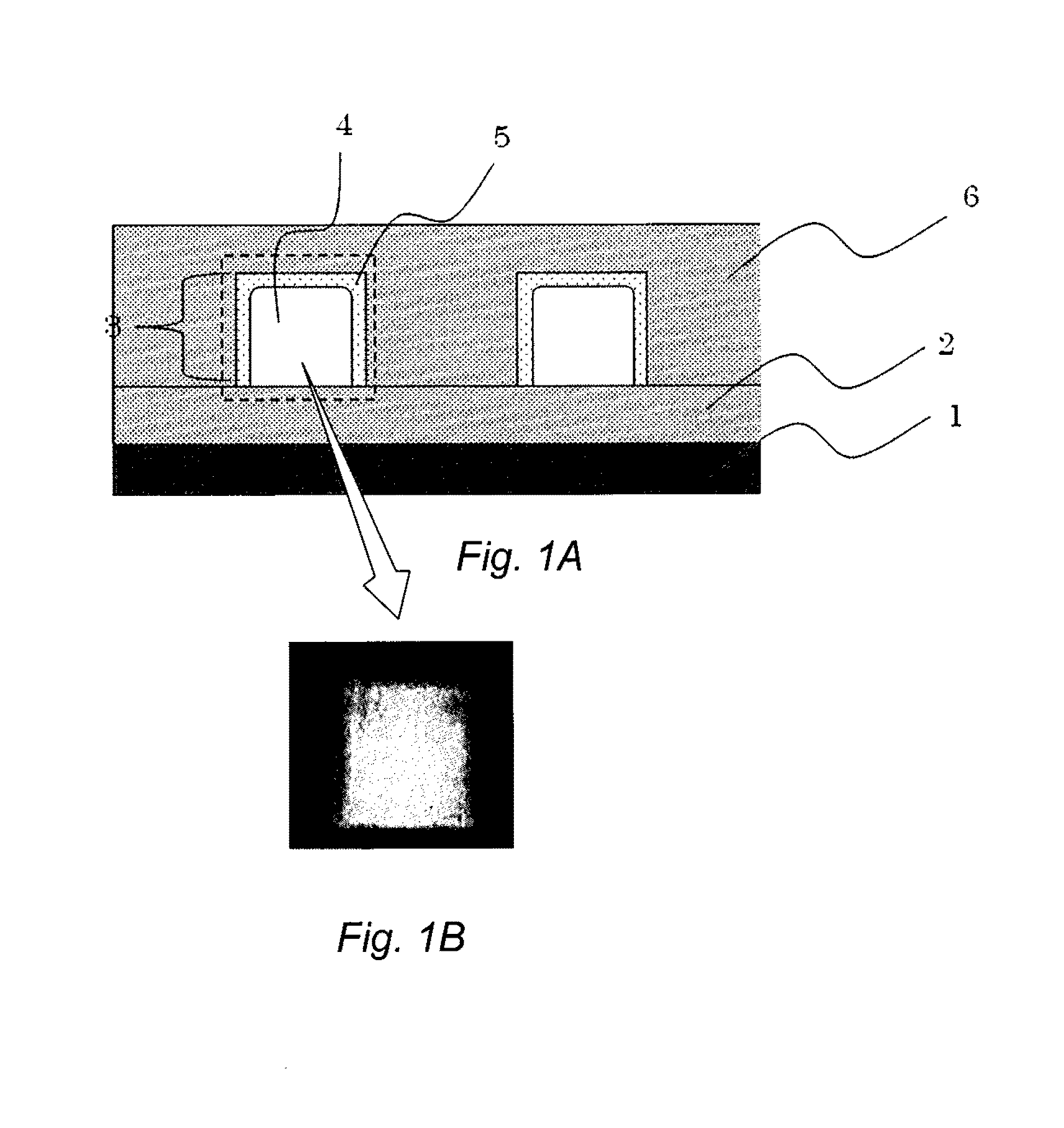
The present invention provides a method for manufacturing an optical member and an optical waveguide having a low optical loss. The provided method is capable of highly accurately controlling the positional configuration of refractive index distribution in the surface layer, including its vicinity, and the center portion of the core pattern in a transparent member. The method for manufacturing the optical member by the present invention has a Process A, in which the transparent member is exposed to a solution and thereby the refractive index of the surface layer of the transparent member exposed to the solution is substantially lower than that of the center portion of the transparent member not exposed to the solution. The substantial lowering of the refractive index of the surface layer is achieved by making the refractive index regulating agent exert its function by being included in the surface layer of the transparent member. The optical waveguide by the present invention has such a feature that surface layers of two or more sides on the circumference of the core pattern forming the core part have a refractive index lower than that of the center portion of the core pattern. The surface layer includes a refractive index regulating agent for lowering the refractive index. Further, a lower clad layer or an upper clad layer, or both, are provided outside the surface layer of low refractive index, wherein the refractive index of these clad layers are lower than that of the surface layer.

Description

TECHNICAL FIELD[0001]The present invention relates to a method for manufacturing optical member; and optical member, transparent member for forming optical member, optical waveguide, and optical module.BACKGROUND OF THE INVENTION[0002]Antireflection members have been used for various applications. In particular, they are used in the main bodies of devices such as displays or in certain members with being pasted thereon in a style of film. In general, the antireflection function of an antireflection film is provided by a multiple-layer of transparent material formed on a transparent substrate. The multiple-layer is composed of an alternate lamination of a high refractive index part and a low refractive index part, each of which parts is made of the transparent material such as metallic oxide. The multiple-layer structure of this kind can be formed generally by a dry deposition method such as the physical vapor deposition (PVD) and the chemical vapor deposition (CVD). These methods ha...

Claims


Application Information

Patent Timeline
IPC IPC(8): G02B6/138G02B6/122G02B6/136B29D11/00
CPCG02B6/138B29D11/00701G02B2006/12157G02B6/136B29K2033/04G02B6/1221B29C2035/0827B29C2035/0833B29D11/00682G02B1/11G02B1/12
Inventor SAKAI, DAICHIUCHIGASAKI, MASAOKURODA, TOSHIHIRO
Owner HITACHI CHEM CO LTD
Learn More