Motor controller
a technology of motor controllers and motors, applied in the direction of electronic commutators, dynamo-electric gear control, dynamo-electric converter control, etc., can solve problems such as inability to correct errors, and achieve the effect of advantageously correcting errors of current sensors
- Summary
- Abstract
- Description
- Claims
- Application Information
AI Technical Summary
Benefits of technology
Problems solved by technology
Method used
Image
Examples
first embodiment
[0074]Embodiments of the vehicle controller are described below. Initially, the first embodiment is described with reference to FIGS. 1 to 9A, 9B, and 9C.
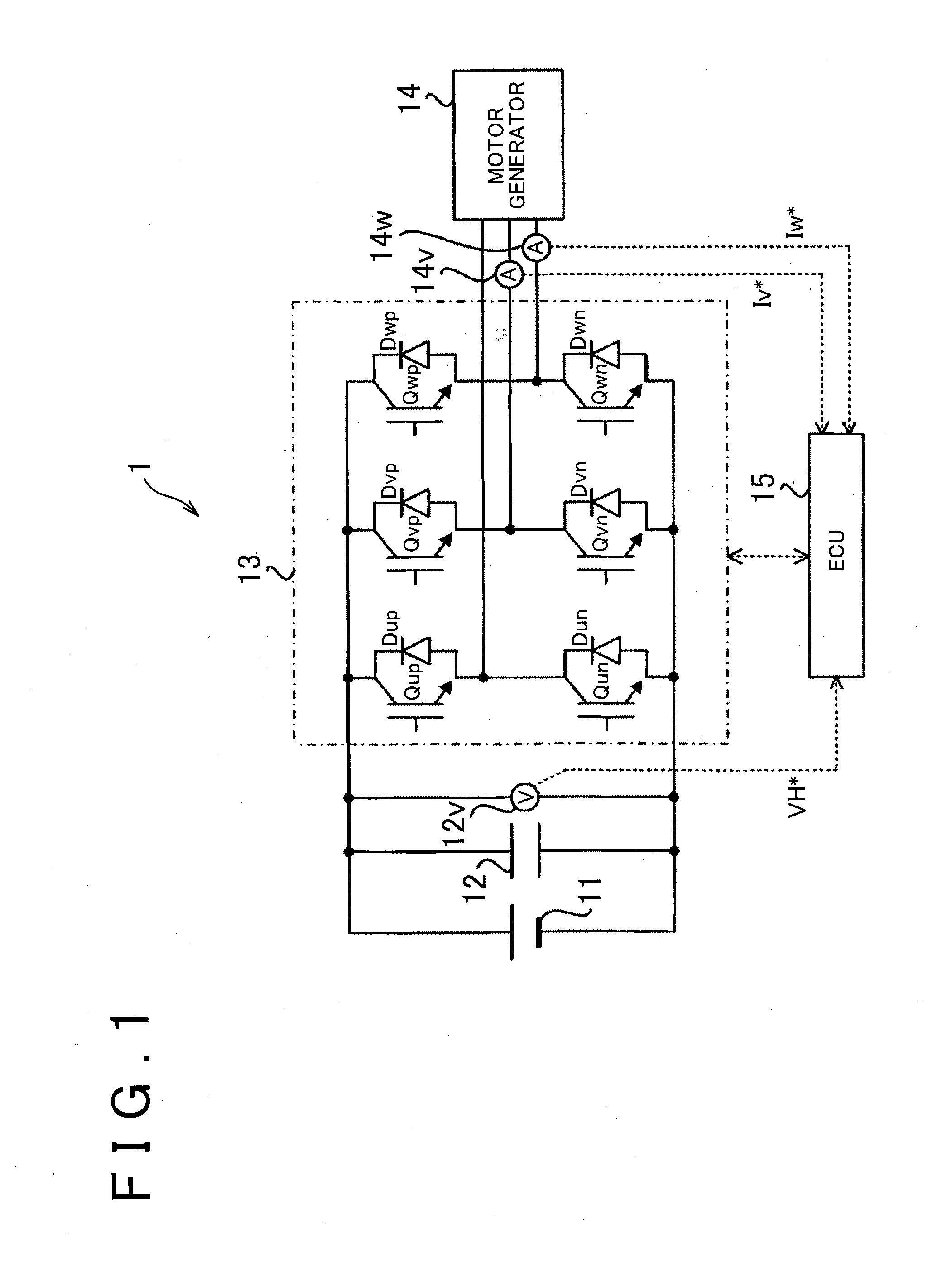
[0075]The configuration of vehicle 1 of the first embodiment is described with reference to FIG. 1. FIG. 1 is a block diagram of the configuration of the vehicle 1 of the first embodiment.
[0076]As shown in FIG. 1, the vehicle 1 is provided with a direct current (DC) power supply 11, a smoothing capacitor 12, a voltage sensor 12v, an inverter 13, which is a specific example of the “power converter”, a motor generator 14, which is a specific example of the “three-phase alternating current (AC) motor”, a V-phase current sensor 14v, a W-phase current sensor 14w, and an electronic control unit (ECU) 15, which is a specific example of the “motor controller”.
[0077]The DC power supply 11 is a chargeable electric storage device. The DC power supply 11 is, for example, a secondary battery (for example, a, nickel metal hydride battery or a li...
second embodiment
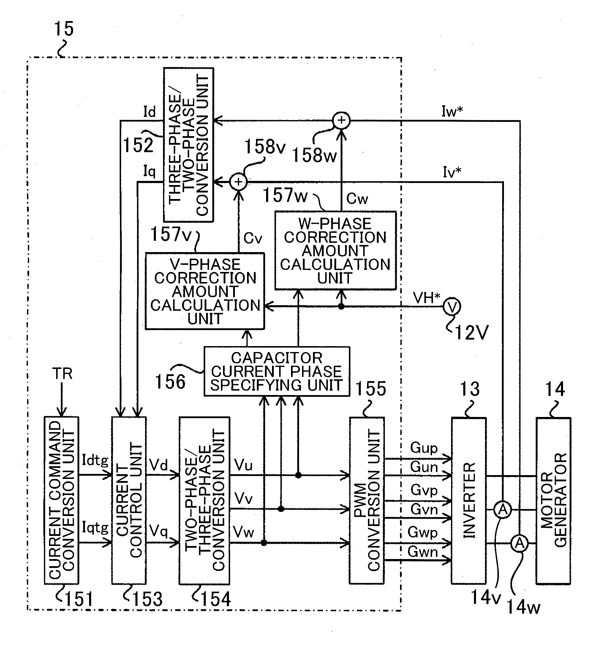
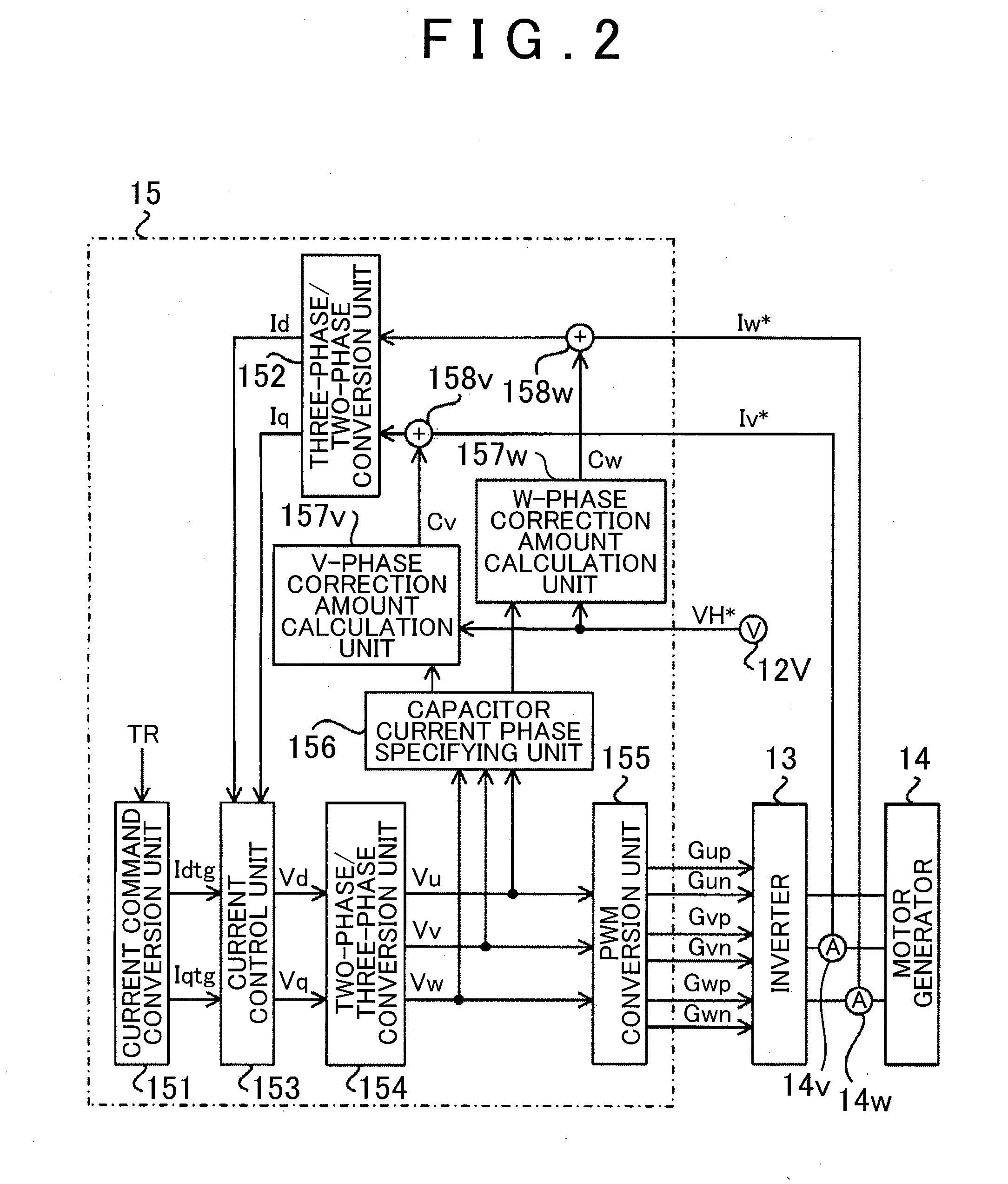
[0156]In the second embodiment, the V-phase correction amount calculation unit 157v calculates the increase / decrease amount (change amount) of the voltage component of a specific frequency that is to be inputted to the V-phase correction amount calculation unit 157v within the time period in which the V phase is specified as the capacitor current phase. Then, the V-phase correction amount calculation unit 157v calculates the V-phase correction amount Cv for correcting the V-phase current detection signal Iv* such that the increase / decrease amount of the voltage component becomes zero.
[0157]In this case, for example, when the voltage component with a specific frequency is the voltage component having a frequency same as the frequency of the three-phase voltage command signals, the V-phase correction amount calculation unit 157v can calculate the V-phase correction amount Cv necessary for correcting the error (more specifically, the offset error) αv included in the V-phase current det...
third embodiment
[0166]Accordingly, in the third embodiment, the voltage-boosting converter 31 performs the voltage boosting operation such that a voltage component obtained by removing the change component of the terminal voltage VH, which is caused by the error αv and the error αw, from the terminal voltage detection signal VH* matches the desired voltage value. For example, the voltage-boosting converter 31 performs the voltage boosting operation such that a voltage component obtained by removing both the voltage component having a frequency same as that of the three-phase voltage command signals (that is, the change component of the terminal voltage VH, which is caused by the offset error) and the voltage component having a frequency twice the frequency of the three-phase voltage command signals (that is the change component of the terminal voltage VH, which is caused by the gain error) from the terminal voltage detection signal VH* matches the desired voltage value. The operation of removing th...
PUM
 Abstract
Description
Claims
Application Information
 - R&D
- Intellectual Property
- Life Sciences
- Materials
- Tech Scout
- Unparalleled Data Quality
- Higher Quality Content
- 60% Fewer Hallucinations
Browse by: Latest US Patents, China's latest patents, Technical Efficacy Thesaurus, Application Domain, Technology Topic, Popular Technical Reports.
© 2025 PatSnap. All rights reserved.Legal|Privacy policy|Modern Slavery Act Transparency Statement|Sitemap|About US| Contact US: help@patsnap.com


