Heat shield film and method of forming heat shield film

a heat shield film and heat shield technology, applied in the direction of machines/engines, mechanical equipment, cylinders, etc., can solve the problems of low volumetric specific heat, low heat insulation film deformation, and low thermal conductivity, and achieve low volumetric specific heat, low thermal conductivity, and high interfacial strength

Inactive Publication Date: 2016-07-14
TOYOTA JIDOSHA KK
View PDF7 Cites 4 Cited by
  • Summary
  • Abstract
  • Description
  • Claims
  • Application Information

AI Technical Summary

Benefits of technology

[0014]In this way, because the heat shield film is diffusion-bonded to the wall surface of the aluminum-based member, the bonding strength of the interface therebetween increases. Because the heat shield film is formed of the porcelain enamel material having a coefficient of linear expansion of 15×10−6 / K to 25×10−6 / K in a temperature range of ordinary temperature to 200° C., the coefficient of linear expansion is substantially equal to a coefficient of linear expansion of the aluminum-based member (depending on the type of alloy, a coefficient of linear expansion of 19×10−6 / K to 23×10−6 / K). Thus, almost no thermal deformation difference occurs therebetween. In this way, because the bonding strength between the heat shield film and the wall surface of the aluminum-based member is high due to diffusion bonding and there is almost no thermal deformation difference between the heat shield film and the member, the effect of preventing interfacial peeling increases.
[0036]As can be understood from the above description, with the heat shield film according to the first aspect of the invention, the heat shield film, formed of the matrix layer made of the porcelain enamel material having a coefficient of linear expansion close to the coefficient of linear expansion of aluminum and the hollow particles dispersed in the matrix layer, is formed on the wall surface of the aluminum-based member, so the heat shield film has a low thermal conductivity, a low volumetric specific heat and a high effect of improving interfacial peeling between the member and the heat shield film. With the method of forming a heat shield film according to the second aspect of the invention, no bubbles are generated in the heat shield film or at the interface between the heat shield film and the member, so it is possible to form the heat shield film having a high film strength and a high interfacial strength.

Problems solved by technology

However, because the above-described ceramics generally have a low thermal conductivity and a high thermal capacity, there occurs a decrease in intake efficiency or knocking (abnormal combustion due to remaining of heat in the combustion chamber) due to a steady increase in surface temperature.
Therefore, the ceramics have not presently become widespread as a film material for the inner wall of the combustion chamber.
Furthermore, in addition to the low thermal conductivity and low thermal capacity, the film desirably has a deformability so as to be able to follow explosion pressure at the time of combustion in the combustion chamber, injection pressure, and repetition of thermal expansion and thermal shrinkage, and is desirably hard to cause, interfacial peeling due to a thermal deformation amount between the film and a matrix of a cylinderblock, or the like.
However, these heat insulation film structures are such that bubbles are formed inside a heat insulation material made of ceramics, or the like, so a high deformability is not expected from the heat insulation film.
Therefore, there can be an inconvenience that the heat insulation film is damaged because of thermal fatigue in process of receiving repeated stress of thermal expansion and thermal shrinkage in the combustion chamber, a thermal deformation difference is easy to increase between the heat insulation film and a base material made of an aluminum matrix, and peeling is easy to occur at the interface between the heat insulation film and the base material.

Method used


Image

  • Heat shield film and method of forming heat shield film
  • Heat shield film and method of forming heat shield film
  • Heat shield film and method of forming heat shield film

Examples


first embodiment

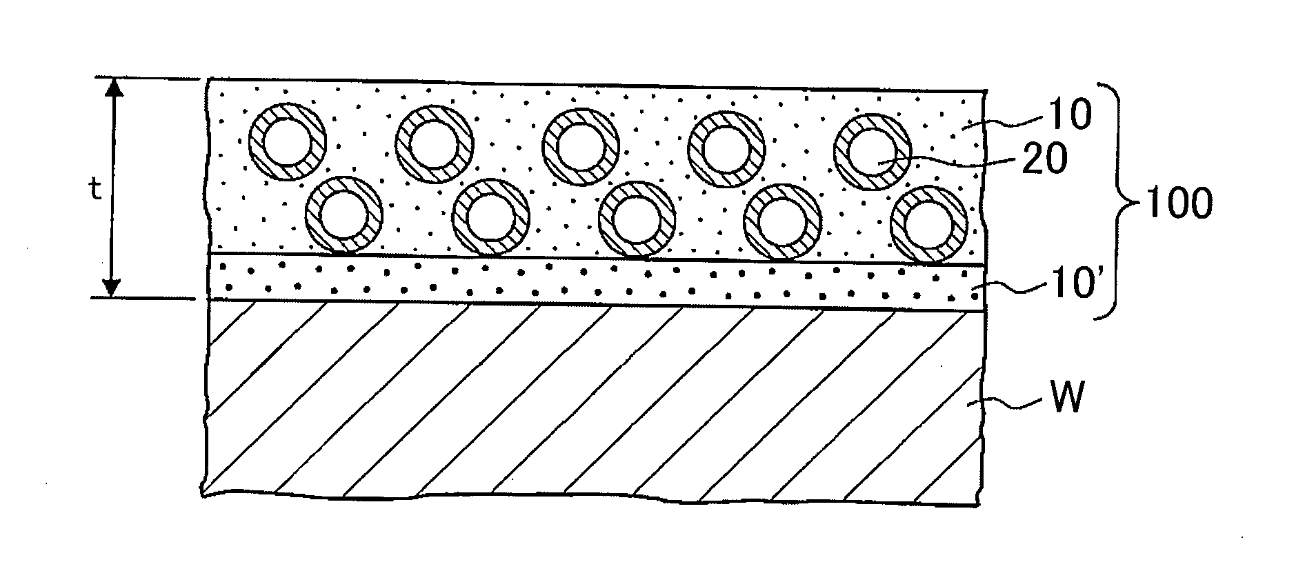
[0053]FIG. 1 is a longitudinal cross-sectional view that shows the heat shield film. An illustrated heat shield film 100 is formed of a matrix layer 10 made of a porcelain enamel material and hollow particles 20 dispersed inside the matrix layer 10. Part of the matrix layer 10 constitutes a diffusion bonding layer 10′, and is formed on a wall surface of an aluminum-based member W. The thickness t of the heat shield film 100 is about 100 μm.

[0054]Because the heat shield film 100 is formed on the wall surface of the aluminum-based member W, a raw material compatible with the aluminum-based member W is employed as the porcelain enamel material forming the matrix layer 10.

[0055]The porcelain enamel material is formed of a material mixing a vanadium-based glass frit with a glaze. The heat shield film 100 has a coefficient of linear expansion of 15×10−6 / K to 25×10−6 / K in a temperature range of ordinary temperature to 200° C., and has a coefficient of linear expansion substantially equal t...

second embodiment

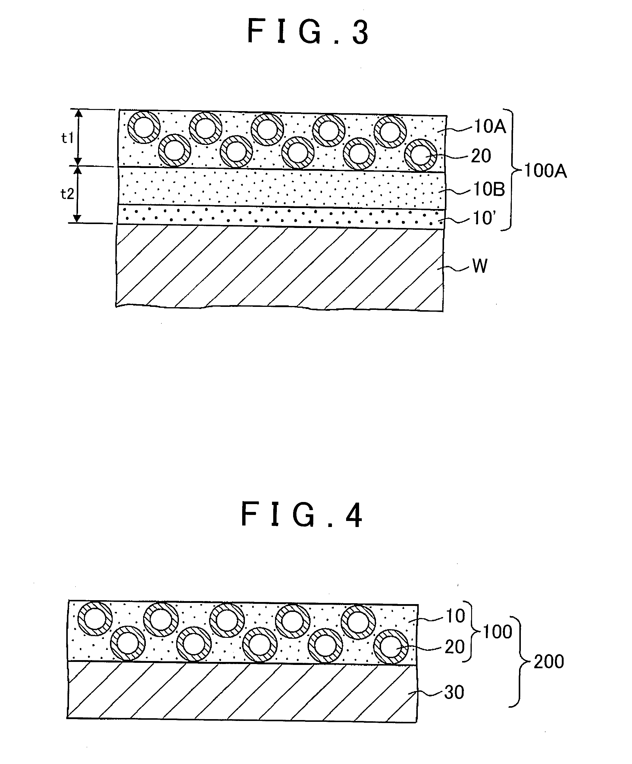
[0064]FIG. 3 is a longitudinal cross-sectional view that shows the heat shield film. An illustrated heat shield film 100A has a two-layer structure formed of an upper layer 10A and a base layer 10B adjacent to the wall surface of the member W (the diffusion bonding layer 10′ is included in the base layer 10B). The base layer 10B contains no hollow particles. Only the upper layer 10A contains the hollow particles 20. Each of the thickness t1 of the upper layer 10A and the thickness t2 of the base layer 10B is about 50 μm. In another embodiment, the base layer also contains the hollow particles, but the content of the hollow particles in the upper layer is relatively large.

[0065]The heat shield film 100A has a two-layer structure formed of the upper layer 10A and the base layer 10B adjacent to the wall surface, and the base layer 10B contains no hollow particles. Therefore, the base layer 10B has a lower firing temperature than the upper layer 10A, so the glass frit of the base layer ...


PUM

PropertyMeasurementUnit
temperatureaaaaaaaaaa
glass transition temperatureaaaaaaaaaa
heat-resistant temperatureaaaaaaaaaa

Abstract

A heat shield film (100) that is formed on a wall surface of an aluminum-based member (W) includes: a matrix layer (10) diffusion-bonded to the wall surface (diffusion bonding layer (10′)), having a coefficient of linear expansion of 15×10−6 / K to 25×10−6 / K in a temperature range of ordinary temperature to 200° C. and made of a porcelain enamel material; and hollow particles (20) dispersed in the matrix layer (10).

Description

BACKGROUND OF THE INVENTION[0001]1. Field of the Invention[0002]The invention relates to a heat shield film that is formed on a wall surface of an aluminum-based member and a method of forming the heat shield film, and, for example, relates to a heat shield film that is formed on part or all of a wall surface facing a combustion chamber of an internal combustion engine and a method of forming the heat shield film.[0003]2. Description of Related Art[0004]An internal combustion engine, such as a gasoline engine and a diesel engine, is mainly formed of an engine block, a cylinder head and a piston. A combustion chamber of the internal combustion engine is defined by a bore face of the cylinder block, a top face of the piston assembled in the bore, a bottom face of the cylinder head and top faces of intake and exhaust valves arranged in the cylinder head. With high-power requirements to recent internal combustion engines, it is important to reduce the cooling losses of the internal comb...

Claims


Application Information

Patent Timeline
Patent Type & Authority Applications(United States)
IPC IPC(8): F02B77/11B22D21/00C23D5/02B22D19/08
CPCF02B77/11C23D5/02B22D21/007B22D19/08C03C8/14C03C8/22C03C2207/08B22D19/0009
Inventor EDA, AKINORI
Owner TOYOTA JIDOSHA KK
Why Eureka
Try Eureka