Silicon carbide semiconductor device and method for producing the same
a silicon carbide and semiconductor technology, applied in the field of silicon cars, can solve the problems of increased manufacturing costs, drain leakage current, and difficulty in perpendicular processing of the side surfaces of the trenches, and achieve the effects of low on-state resistance, high switching speed, and high withstand voltag
- Summary
- Abstract
- Description
- Claims
- Application Information
AI Technical Summary
Benefits of technology
Problems solved by technology
Method used
Image
Examples
first embodiment
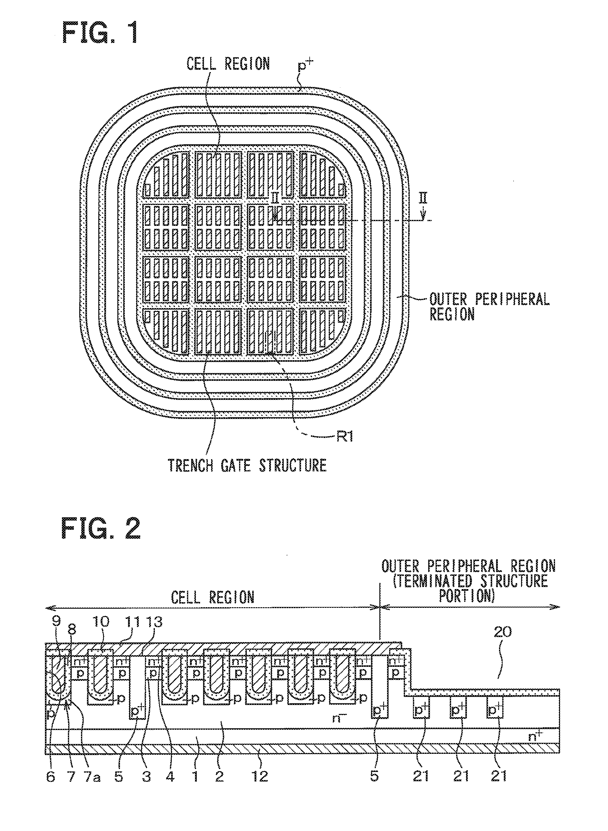
[0030]A first embodiment of the present disclosure will be described. In this case, an SiC semiconductor device formed with an n-channel inversion type MOSFET as a semiconductor switching element with a trench gate structure will be described as an example.
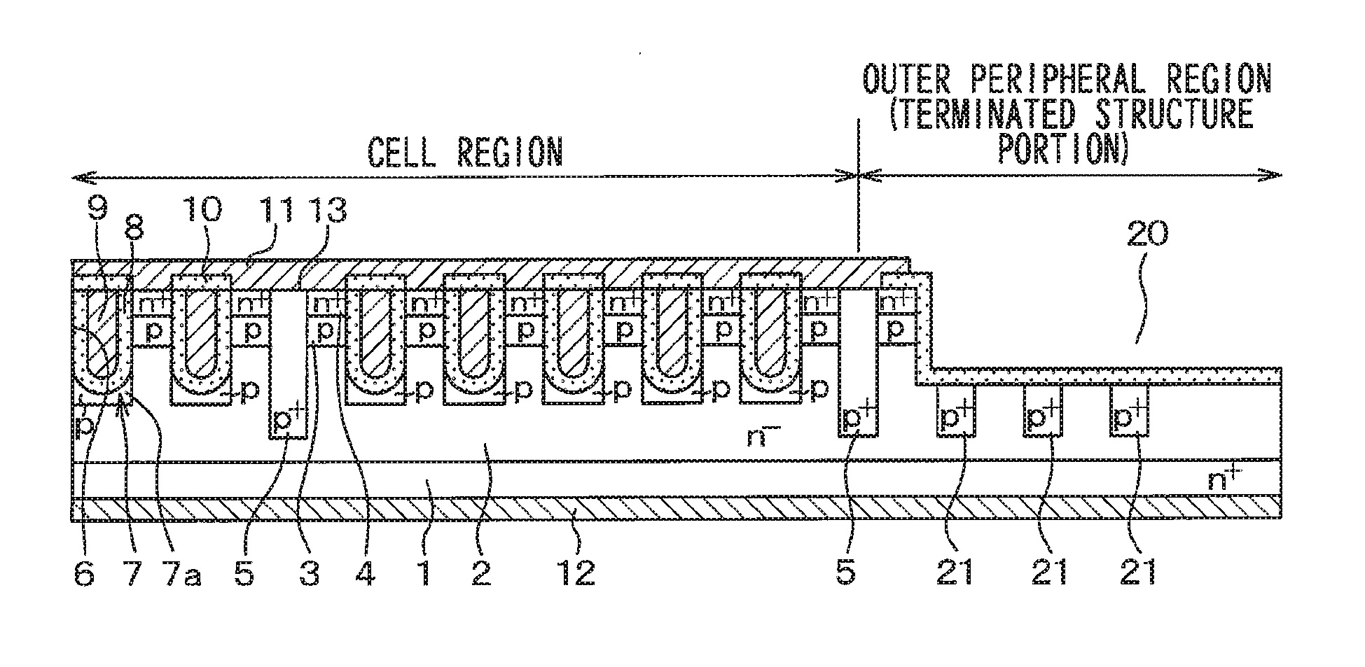
[0031]An SiC semiconductor device shown in FIG. 1 has a cell region formed with a semiconductor element and an outer peripheral region (terminated structure region) provided with an outer peripheral withstand voltage structure surrounding the cell region. In the present embodiment, the SiC semiconductor device has the MOSFET with an inversion type trench gate structure as the semiconductor element.
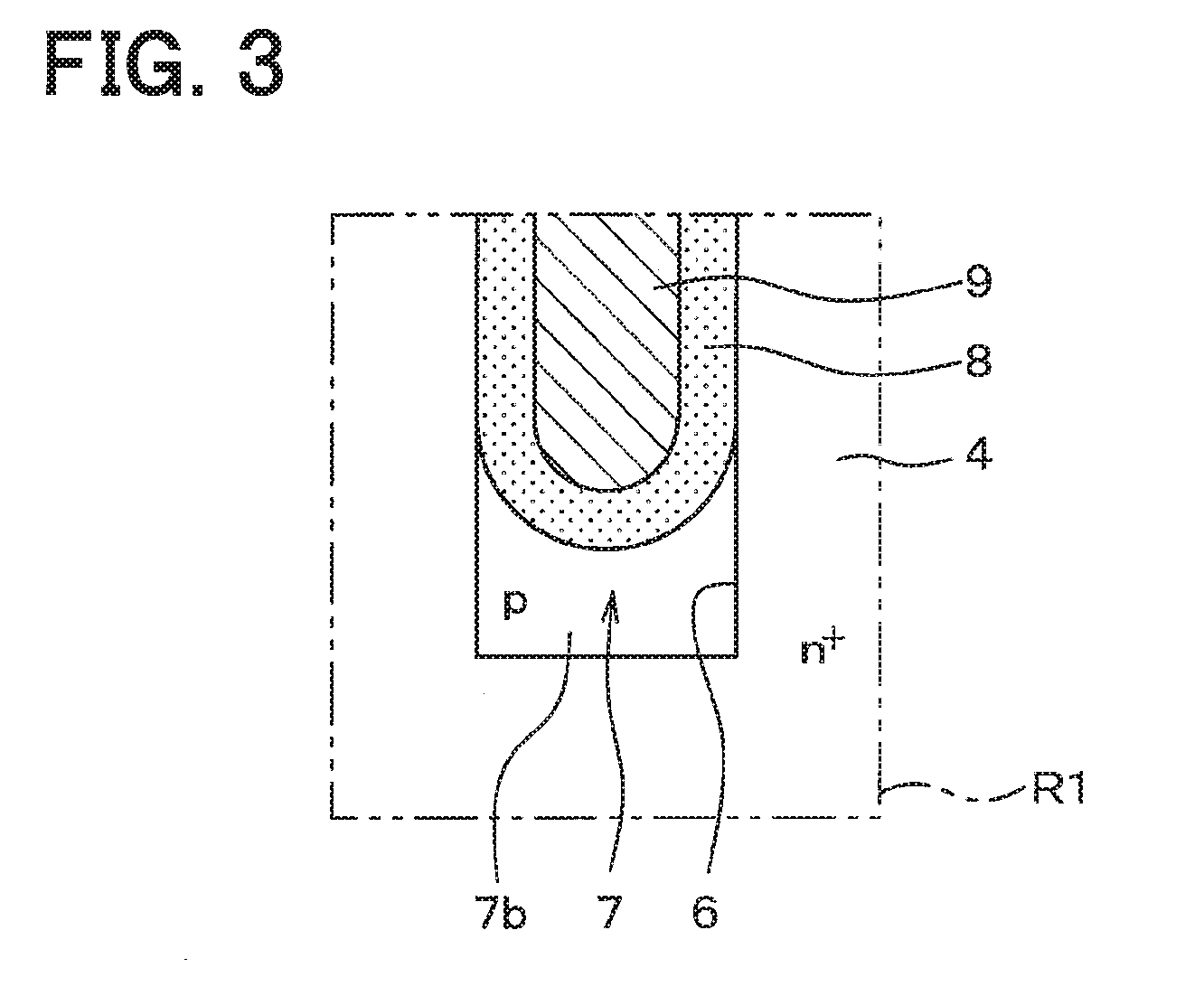
[0032]As shown in FIG. 2, the SiC semiconductor device employs a semiconductor substrate in which an n− type drift layer 2, a p type base region 3, and an n+ type source region 4, which are made of SiC, are epitaxially grown on a main surface of an n+ type substrate 1 made of SiC.
[0033]The n+ type substrate 1 is, for example, 1.0×10¹⁹ / cm...
second embodiment
[0070]A second embodiment of the present disclosure will be described. In the present embodiment, the structure of the p+ type deep layer 5 is modified from that of the first embodiment. The others are similar to the first embodiment, and thus only the part different from the first embodiment will be described.
[0071]The SiC semiconductor device shown in FIG. 7 also includes the cell region in which a semiconductor element is formed and the outer peripheral region. However, the layout of the p+ type deep layer 5 formed in the cell region is different from that of the first embodiment. Specifically, as shown in the enlarged view of FIG. 8, the trench gate structure is divided into plural sections in the longitudinal direction, and the p+ type deep layer 5 is arranged to overlap the end portion of each of the divided trench gate structures. The p+ type deep layer 5 is formed into a line shape to continuously intersect with the divided trench gate structures that are arranged in paralle...
third embodiment
[0075]A third embodiment of the present disclosure will be described. In the present embodiment, the p+ type deep layer 5 is eliminated from the structure of the first embodiment, and the structure of the trench gate structure is modified from that of the first embodiment. The others are similar to those of the first embodiment. Therefore, only the parts different from the first embodiment will be described.
[0076]The SiC semiconductor device shown in FIG. 11 also includes the cell region in which the semiconductor element is formed and the outer peripheral region. However, the p+ type deep layer 5 is not formed in the cell region. In the trench gate structure of the present embodiment, as shown in FIG. 12, the depth of the trench 6 is increased, and, at the bottom portion and the end portions of the trench 6, the p type SiC layer 7 (the bottom p type layer 7a and the end p type layers 7) is formed and the thickness of the gate insulation film 8 is increased. The upper surface of a r...
PUM
 Abstract
Description
Claims
Application Information
 - R&D
- Intellectual Property
- Life Sciences
- Materials
- Tech Scout
- Unparalleled Data Quality
- Higher Quality Content
- 60% Fewer Hallucinations
Browse by: Latest US Patents, China's latest patents, Technical Efficacy Thesaurus, Application Domain, Technology Topic, Popular Technical Reports.
© 2025 PatSnap. All rights reserved.Legal|Privacy policy|Modern Slavery Act Transparency Statement|Sitemap|About US| Contact US: help@patsnap.com


