
Magnetohydrodynamic Microfluidic Systems Including Modified Electrodes And Methods Of Using The Same

a microfluidic and hydrodynamic technology, applied in the field of magnetic hydrodynamic microfluidic systems including modified electrodes and methods of using the same, can solve the problems of low concentration limits, contamination and interference with analyte detection and biocompatibility of the pumping system, and the inability to achieve the highest possible velocities, so as to reduce the overall cost of the system, reduce or eliminate the need for adding redox species, and increase portability and accessibility

Inactive Publication Date: 2016-05-26
THE BOARD OF TRUSTEES OF THE UNIV OF ARKANSAS
View PDF0 Cites 7 Cited by
  • Summary
  • Abstract
  • Description
  • Claims
  • Application Information

AI Technical Summary

Benefits of technology

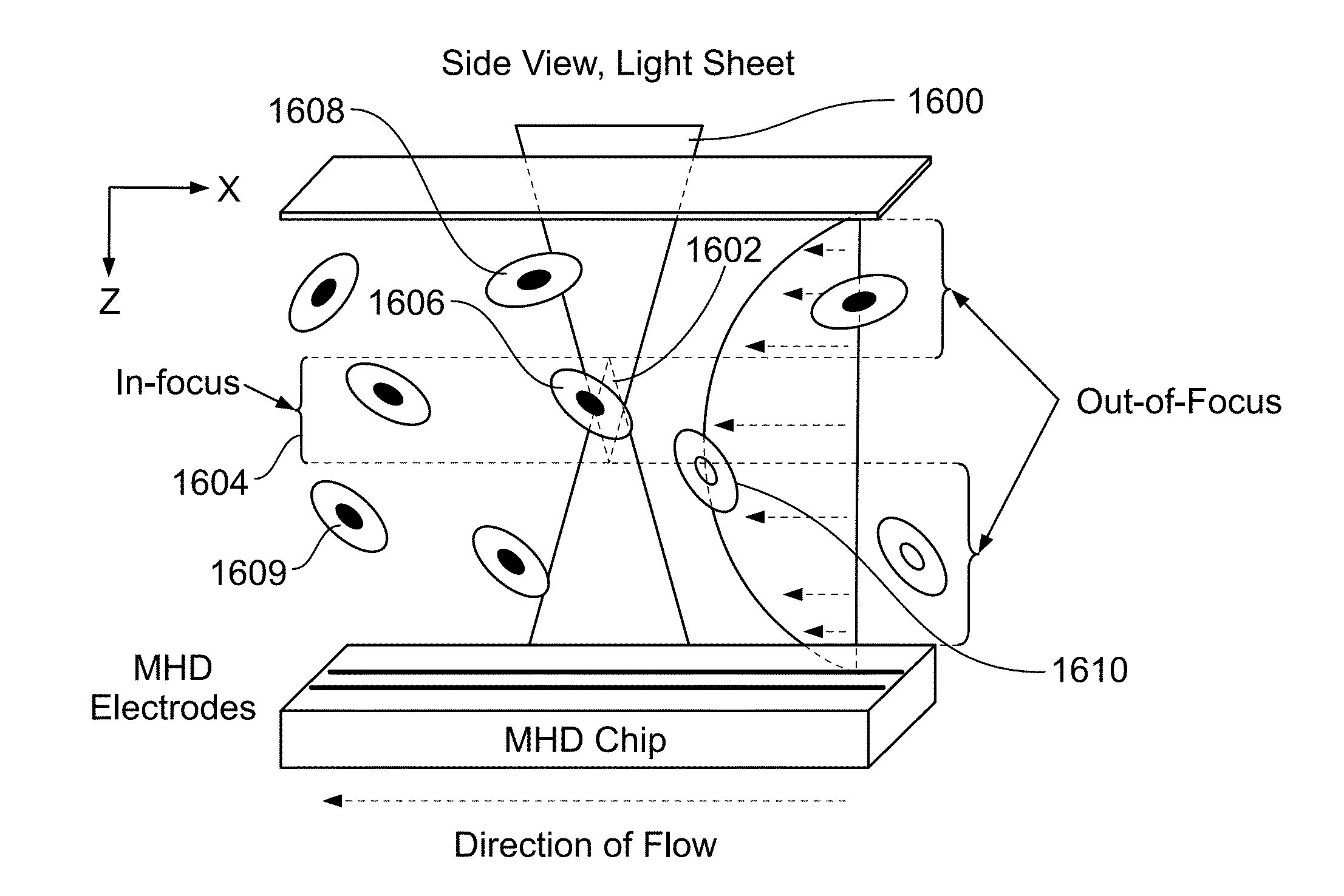
The present invention is a low-cost screening tool for myelosuppresion or infection that combines optofluidics and staining of leukocytes in whole blood. In another aspect, the invention concerns an imaging cytometry device that utilizes MHD fluid transport and a high resolution linear imaging microscope. This innovative method has the potential to be transformative across a broad range of biomedical applications by providing a confocal microscopy platform with no moving parts capable of continuous high spatiotemporal resolution imaging of cytology specimens.

Problems solved by technology

This method, when applied to aqueous solutions corroded electrodes and produced bubbles from the electrolysis of water, which interrupted fluid flow.
However, the introduction of redox species raises concerns about the risk of contamination and interference with analyte detection and with the biocompatibility of the pumping system.
However, the use of low concentrations limits the highest possible velocities that can be achieved.
Chemotherapy typically leaves the patient myelosuppressed and susceptible to treatment-induced infection.
A challenge for oncologists and chemotherapy patients is treatment-induced myelosuppression.
Monitoring and diagnosing this effect requires multiple draws by painful venipuncture and expensive non-portable hematology analyzers; which themselves require multiple reagents for analysis and a trained lab technician for operation.
These limitations restrict the ability to diagnose and monitor myelosuppression at the point-of-care and in low-resource settings.
Although these approaches have many benefits, additional reductions in cost are necessary since many POC diagnostic systems rely on reagents that are difficult and expensive to produce, store and package effectively.
Conventional flow cytometry systems require significant investment and have limited portability, and are generally limited to exogenous targeting of cellular proteins, requiring a priori knowledge of the target of interest.
Vital clinical applications, such as detection of extremely rare cells in heterogeneous samples, such as circulating tumor cells or cells with intracellular parasites, such as in malaria, make conventional microscopy of a small number of cells unreliable due to under-sampling bias and the need to screen vast numbers of high power fields.
Conventional flow cytometry methods are able to screen large numbers of cells but are generally insensitive to intrinsic morphologic or metabolic changes within individual cells, in addition to the lack of portability of these devices.
However, like flow cytometry systems, these are typically limited in scope and insensitive to endogenous reporters of metabolism, such as intrinsic nicotinamide adenine dinucleotide (NADH) or flavin adenine dinucleotide (FAD) fluorescence.
Furthermore, due to conventional imaging approaches utilizing complex scanning mirrors and photomultiplier tubes, these systems are generally unsuitable for low-power, and portable operation.
This is not an automated approach and requires several steps and skill to handle the sample and perform the staining.
Mechanical pumping, such as the use of syringe pumps, requires equipment exterior to the viewing device, moving parts, adds bulk and channels to direct fluid flow, and produces a non-uniform, parabolic flow profile.

Method used


Image

  • Magnetohydrodynamic Microfluidic Systems Including Modified Electrodes And Methods Of Using The Same
  • Magnetohydrodynamic Microfluidic Systems Including Modified Electrodes And Methods Of Using The Same
  • Magnetohydrodynamic Microfluidic Systems Including Modified Electrodes And Methods Of Using The Same

Examples


Embodiment Construction

[0076]Detailed embodiments of the present invention are disclosed herein; however, it is to be understood that the disclosed embodiments are merely exemplars of the invention, which may be embodied in various forms. Therefore, specific structural and functional details disclosed herein are not to be interpreted as limiting, but merely as a representative basis for teaching one skilled in the art to variously employ the present invention in virtually any appropriately detailed method, structure or system. Further, the terms and phrases used herein are not intended to be limiting, but rather to provide an understandable description of the invention.

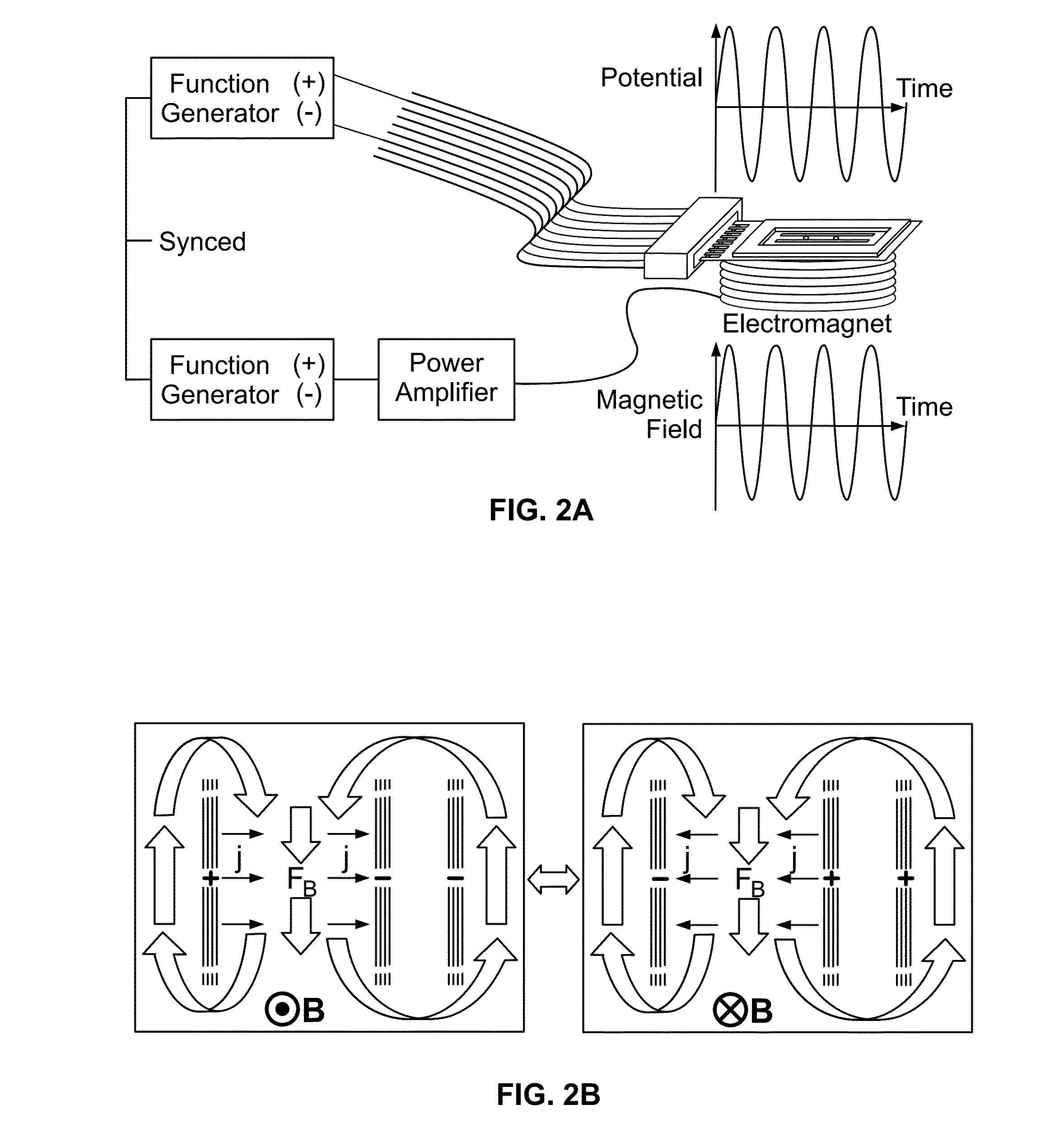
[0077]The magnetohydrodynamics (MHD) microfluidic system of the present invention is useful for pumping fluid that includes a current carrying species. The MHD microfluidic system includes an electromagnet that generates a magnetic field, at least two electrodes, at least one of which may be a modified electrode, a cell, an electric field g...


PUM

PropertyMeasurementUnit
frequencyaaaaaaaaaa
lengthaaaaaaaaaa
thicknessaaaaaaaaaa

Abstract

A magnetohydrodynamic microfluidic system and a method of pumping a fluid using a magnetohydrodynamic system are disclosed. The method includes applying at least one of an electric current and an electric voltage to a first modified electrode and a second electrode to generate an ionic current between the first modified electrode and the second electrode and to cause a current carrying species to move to or from the modified electrode, applying a magnetic field perpendicular to an ionic current vector, the magnetic field and the ionic current combining to induce flow of the fluid in a direction perpendicular to the magnetic field and the ionic current vector, and maintaining fluid flow by recharging the modified electrode.

Description

RELATED APPLICATIONS[0001]This application claims the benefit of U.S. Provisional Application No. 62 / 084,466 filed on Nov. 25, 2014 and U.S. Provisional Application No. 62 / 152,117 filed on Apr. 24, 2015, both of which are herein incorporated by reference.STATEMENT REGARDING FEDERALLY SPONSORED RESEARCH & DEVELOPMENT[0002]Not applicable.INCORPORATION BY REFERENCE OF MATERIAL SUBMITTED ON A COMPACT DISC[0003]Not applicable.BACKGROUND OF THE INVENTION[0004]The present invention is directed to, among other things, the miniaturization of analytical techniques from a full lab or bench top scale to a lab-on-a-chip (LOAC) device which promises to improve portability, power consumption, reagent and waste volumes, automation, and analysis time. LOAC devices show promise for revolutionizing analysis needed in medical diagnosis, environmental field studies, genomic studies, and for performing synthetic reactions. One of the aspects of LOAC applications is the microfluidics, i.e., the manipulati...

Claims


Application Information

Patent Timeline
Patent Type & Authority Applications(United States)
IPC IPC(8): G01N27/447G01N15/14B01L3/00
CPCG01N27/44791B01L3/502715B01L3/502761B01L3/50273G01N15/1475G01N27/44786G01N2015/0065B01L2300/0654B01L2200/0647B01L2300/0645B01L2400/0463G01N2015/1486B01L2400/043F04B19/006B01L2300/0816B01L2400/0415G01N15/147G01N27/447B01F33/3032G01N2015/016G01N15/1433
Inventor FRITSCH, INGRIDNASH, CHRISTENAKUMAR, SAIMULDOON, TIMOTHYBALACHANDRAN, KARTIKCLAYCOMB, ADAIRGERNER, MATTHEW D.HUTCHESON, JOSHUAKHAN, FOYSAL Z.POWLESS, AMYPRIETO, SANDRASCRAPE, PRESTON G.WESTON, MELISSA C.
Owner THE BOARD OF TRUSTEES OF THE UNIV OF ARKANSAS
Learn More