
Contamination Filter for Mass Spectrometer

a contamination filter and mass spectrometer technology, applied in the field of mass spectrometry, can solve the problems of reducing the transmission of ions of interest, not always feasible or possible to use a high-resolution mass analyzer to separate interfering, and ion loss, so as to maintain the peak performance of the mass spectrometer system over a longer period of time, improve the signal-to-noise, and reduce the amount of unwanted charged materials

Active Publication Date: 2016-04-28
DH TECH DEVMENT PTE
View PDF4 Cites 9 Cited by
  • Summary
  • Abstract
  • Description
  • Claims
  • Application Information

AI Technical Summary

Benefits of technology

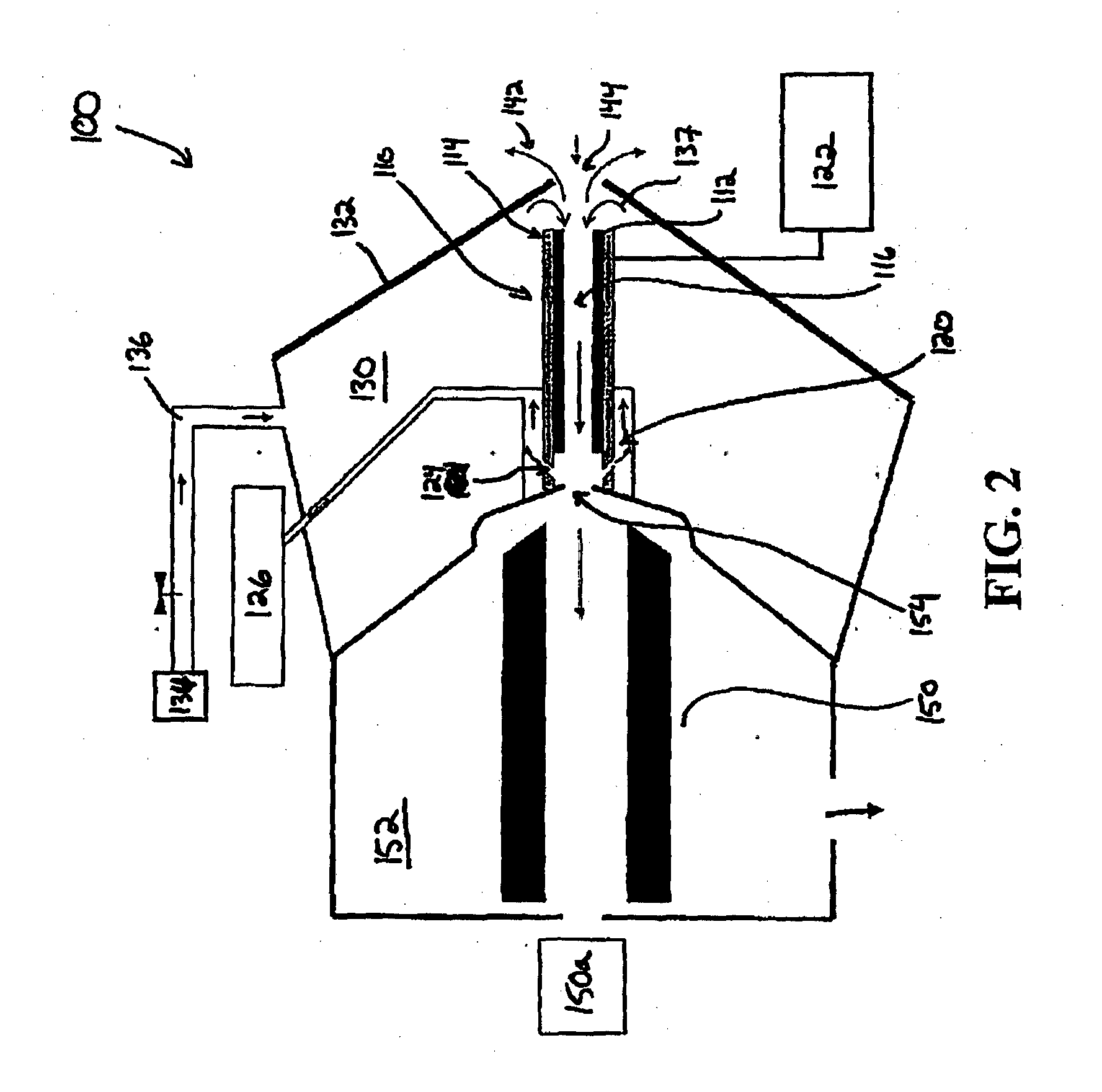
The patent describes a method and system for improving the performance of a mass spectrometer by reducing the amount of unwanted charged material from entering the vacuum system. This is achieved by configuring the ion mobility spectrometer to filter out high mass ions and low mass ions, which can be generated by the solvent molecules in a liquid sample. By eliminating these ions, the signal-to-noise of the mass analyzer is improved, and its sensitivity is maximized while maintaining peak performance over longer periods of time and during heavy use. The system includes a mass analyzer located in a high vacuum chamber, with a region of defocusing electric fringe fields for deflecting charged clusters and debris, and a high volumetric gas flow for transporting ions to the mass spectrometer with minimal loss of ions in a specific m / z range.

Problems solved by technology

Despite advances in MS that have enabled high-resolution mass analyzers to distinguish target species from interfering species within about 0.01 Th, it is not always feasible or possible to use a high-resolution mass analyzer to separate interfering species, for example, due to availability, cost, and / or experimental conditions.
However, operating parameters for ion mobility spectrometers, however, are conventionally configured to optimize the resolution of the various charged species generated from the sample (e.g., to separate isobaric species), often at the expense of decreased transmission of ions of interest.
Moreover, the effects of ion mobility conditions on particular species can be unpredictable and often lead to ion loss (i.e., decreased signal / sensitivity).
Additionally, the ion optics and other mass analyzer components, which are located deep inside high-vacuum chambers where ion trajectories can be precisely controlled by electric fields, are delicate and prone to fouling by the excessive sample loads and debris generated by atmospheric pressure ion sources.
The undesirable transport of contaminating ions and charged particles from the atmospheric pressure source region to the high-vacuum chamber of a mass spectrometer can also result in contamination of ion optics within the intermediate pumping stages of a differentially pumped mass spectrometer.
Such contamination can not only interfere with the mass spectrometric analysis, but also lead to increased costs or decreased throughput necessitated by the cleaning of critical components within the high-vacuum chamber and intermediate pressure regions.
The separation of isobaric species is an example of something a DMS device can do in many cases but a mass spectrometer cannot.
Transmission efficiency tends to run counter to both resolution and peak capacity.
That is in order to maximize resolution and peak capacity, the transmission efficiency is compromised.
The RF waveform is drawn as an idealized square wave but not all DMS power supplies are designed to deliver square wave functions for practical reasons related to power consumption.
Improved resolution is observed with increasing flight time; however the peak intensity decreases as a result of increased ion losses due to diffusion processes in the mobility analyzer.
A practical limit is reached when the field between the cells (V / mm) reaches the discharge limit causing a breakdown of the transport gas and electrical arcing between the electrodes.

Method used


Image

  • Contamination Filter for Mass Spectrometer
  • Contamination Filter for Mass Spectrometer
  • Contamination Filter for Mass Spectrometer

Examples


Embodiment Construction

[0068]It will be appreciated that for clarity, the following discussion will explicate various aspects of embodiments of the applicants' teachings, while omitting certain specific details wherever convenient or appropriate to do so. For example, discussion of like or analogous features in alternative embodiments may be somewhat abbreviated. Well-known ideas or concepts may also for brevity not be discussed in any great detail. The skilled person will recognize that some embodiments of the applicants' teachings may not require certain of the specifically described details in every implementation, which are set forth herein only to provide a thorough understanding of the embodiments. Similarly it will be apparent that the described embodiments may be susceptible to alteration or variation according to common general knowledge without departing from the scope of the disclosure. The following detailed description of embodiments is not to be regarded as limiting the scope of the applican...


PUM


Abstract

Methods and systems for performing mass spectrometry are provided herein. In accordance with various aspects of the applicants' teachings, the methods and systems can utilize an ion mobility spectrometer operating at atmospheric or low-vacuum pressure to remove the major contributors to the contamination and degradation of critical downstream components of a mass spectrometer located within a high-vacuum system (e.g., ion optics, mass filters, detectors), with limited signal loss.

Description

RELATED APPLICATIONS[0001]This application claims priority to U.S. provisional application No. 61 / 838,185 filed on Jun. 21, 2013, entitled “Contamination Filter for Mass Spectrometer,” which is incorporated herein by reference in its entirety and to U.S. provisional application No. 62 / 014,657 filed on Jun. 19, 2014, entitled “Contamination Filter for Mass Spectrometer,” which is incorporated herein by reference in its entirety.FIELD[0002]The invention generally relates to mass spectrometry, and more particularly to methods and apparatus utilizing an ion mobility spectrometer to remove contamination and prevent degradation of downstream components of a mass spectrometer operating in a high-vacuum chamber.INTRODUCTION[0003]Mass spectrometry (MS) is an analytical technique for determining the elemental composition of test substances with both qualitative and quantitative applications. For example, MS can be useful for identifying unknown compounds, determining the isotopic composition ...

Claims


Application Information

Patent Timeline
IPC IPC(8): H01J49/00G01N27/62
CPCH01J49/004G01N27/624H01J49/0031H01J49/145H01J49/165G01N27/623H01J49/0422
Inventor COVEY, THOMAS R.SCHNEIDER, BRADLEY B.
Owner DH TECH DEVMENT PTE
Learn More