
Apparatus for channel equalization using multi antenna and method thereof

a channel equalization and antenna technology, applied in pulse manipulation, pulse technique, instruments, etc., can solve the problems of significant increase in hardware complexity, severe distortion of signals arriving at the receiver, and signal interference that causes strong distortion, so as to enhance the signal-to-noise ratio of the final output and facilitate equalization

Inactive Publication Date: 2006-02-16
LG ELECTRONICS INC
View PDF2 Cites 18 Cited by
  • Summary
  • Abstract
  • Description
  • Claims
  • Application Information

AI Technical Summary

Benefits of technology

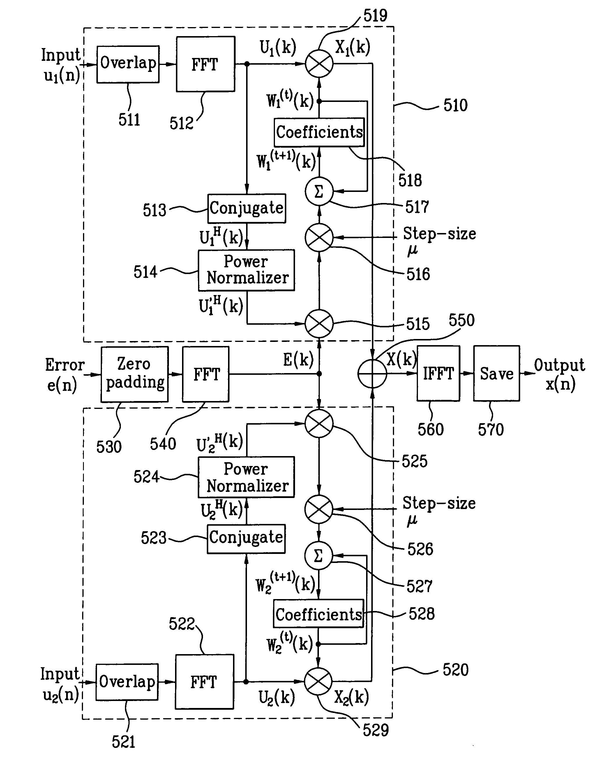
[0053] Therefore, by the present invention, channel equalization is performed using a plurality of the antennas, whereby a signal to noise ratio of a final output is enhanced and whereby a signal of a severely distorted channel is easily equalized.

Problems solved by technology

In doing so, interfering with signals passing through the transport channel of multi-path, the signal arriving at the receiver is severely distorted.
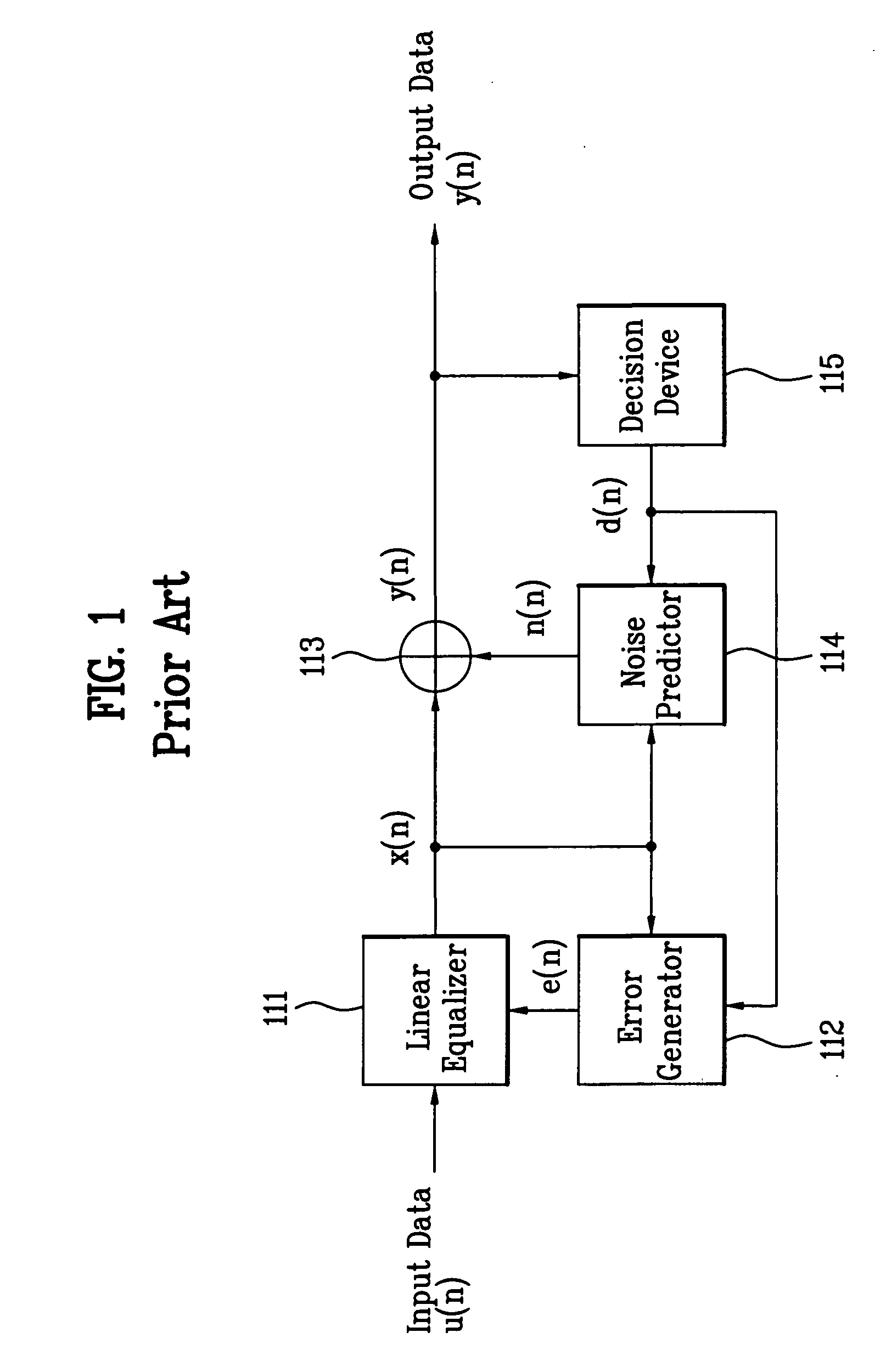
The decision feedback equalizer, which has less noise increment and includes an infinite impulse response (IIR) filter, is advantageous in compensating signal distortion due to a time delay corresponding to length of the filter but is disadvantageous in a problem of instability due to incorrect decision.
In case of receiving broadcasting in the urban center or room, signal interference brings about strong distortion.
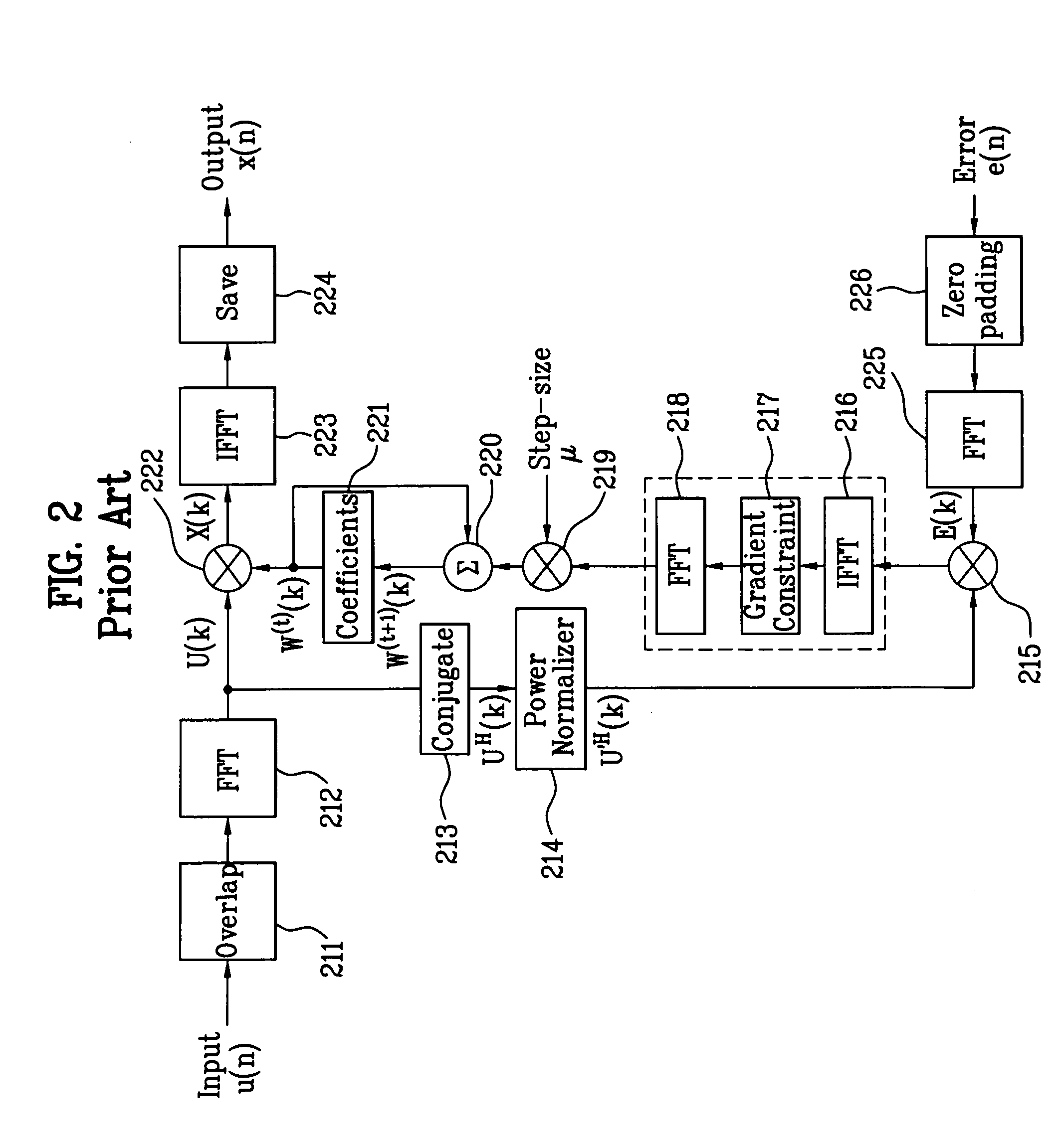
If a linear equalizer is implemented in a time domain, hardware complexity is raised considerably high.
So, like the case that a signal reflected via various paths of the urban center, the indoor space and the like is received, noise amplification is raised in the channel having severe distortion.
Hence, it is difficult to compensate signal distortion in the related art equalizer.

Method used


Image

  • Apparatus for channel equalization using multi antenna and method thereof
  • Apparatus for channel equalization using multi antenna and method thereof
  • Apparatus for channel equalization using multi antenna and method thereof

Examples


Embodiment Construction

[0064] Reference will now be made in detail to the preferred embodiments of the present invention, examples of which are illustrated in the accompanying drawings.

[0065] Besides, the terms used in the present invention are mainly selected from currently usable global and general terms. Yet, most appropriate terms are arbitrarily used by the applicant to keep up with the appearance of new technologies. And, the meanings of the arbitrarily used terms will be clearly explained in the corresponding description. Hence, in apprehending the present invention, the present invention should be understood not by the simple names of the terms but by the meanings of the terms.

[0066]FIG. 4 is a block diagram of a predictive decision feedback equalizer using multi-antenna according to the present invention.

[0067] Referring to FIG. 4, a predictive decision feedback equalizer (pDFE) according to the present invention performs equalization using a plurality of linear equalizers 411 and 412 and then...


PUM


Abstract

The present invention provides an apparatus for channel equalization and method thereof, by which a digital signal received via a plurality of antennas is equalized. The present invention includes receiving digital transmission signals using a plurality of antennas, respectively, initializing equalizer coefficients and equalizing the received signals respectively, adding the equalized signals together, predicting a noise amplified in the equalizing step, and generating a final output signal by removing the predicted noise from a value resulting from adding the equalized signals together. Therefore, the present invention performs equalization using a plurality of antennas, thereby enhancing the signal to noise ratio of the final output and facilitating the equalization of the severely distorted channel.

Description

[0001] This application claims the benefit of the Korean Application No. 10-2004-0063471 filed on Aug. 12, 2004 which is hereby incorporated by reference. BACKGROUND OF THE INVENTION [0002] 1. Field of the Invention [0003] The present invention relates to channel equalization, and more particularly, to an apparatus for channel equalization and method thereof, by which a digital signal received via a plurality of antennas is equalized. [0004] 2. Discussion of the Related Art [0005] Generally, a digital transceiver system maps digital information (e.g., voice, data and video) of a transmitter into symbols, converts each of the symbols to an analog signal proportional to a size or phase, and then transmits the analog signal to a receiver over a transport channel. [0006] In doing so, interfering with signals passing through the transport channel of multi-path, the signal arriving at the receiver is severely distorted. Hence, an equalizer is needed for channel compensation to restore an ...

Claims


Application Information

Patent Timeline
Patent Type & Authority Applications(United States)
IPC IPC(8): H03H7/30H04K1/10H04B7/08H04B1/10
CPCH04B7/0842H04L2025/03426H04L25/03159H04B7/0845H04N7/015
Inventor KIM, BYOUNG GILLCHOI, IN HWANKANG, KYUNG WONSUH, YONG HAKKIM, WOO CHAN
Owner LG ELECTRONICS INC
Learn More