
Device and method for depositing a granular material in additive manufacture

a technology of additive manufacturing and granular material, which is applied in the direction of additive manufacturing processes, manufacturing tools, and applying layer means, etc., can solve the problems of increasing the cost of the machine, the thickness of the layer is not directly uniform, and the difficulty of obtaining a uniform layer of thickness

Pending Publication Date: 2022-11-03
ECOLE CENTE DE NANTES
View PDF0 Cites 1 Cited by
  • Summary
  • Abstract
  • Description
  • Claims
  • Application Information

AI Technical Summary

Benefits of technology

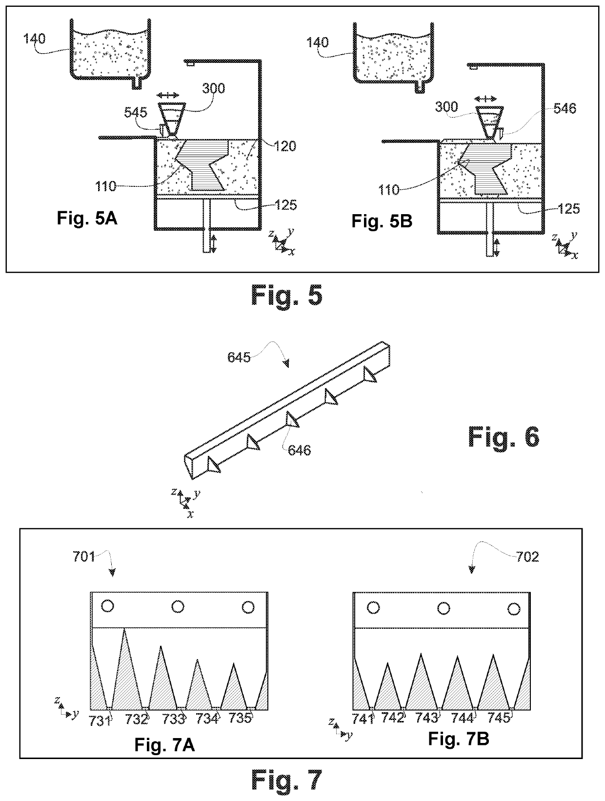
The invention describes a device that deposits material strips close to each other, making it easy to evenly distribute them on a surface. The device has no mobile dosing device and uses a special connection between the compartments that prevents any material residue after emptying the hopper. This allows different materials to be deposited without cleaning the hopper. The device also includes a scraper with reliefs to help equalize the deposited layer. These features reduce friction between the material and the hopper, allowing for more open angles in the discharge portions and bottom walls while still maintaining a steady flow of material. The result is a reduction in the vertical bulk of the hopper.

Problems solved by technology

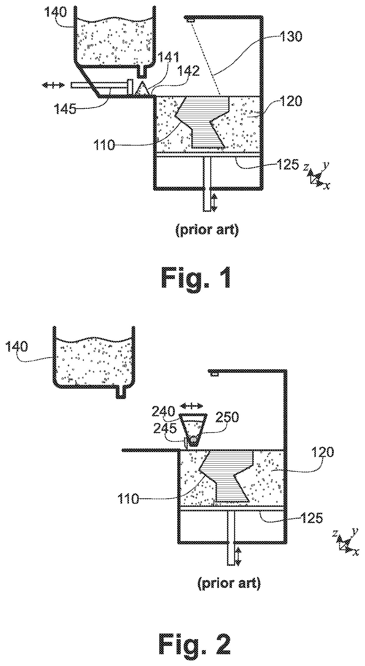
The operation of depositing the layer of granular material according to this method, as well as its variants, poses difficulties for obtaining a uniform layer of thickness, particularly, but not exclusively, when the surface of the material bed is significant.
The pile (141) of material is initially more difficult to push and to distribute than at the end of the distribution, such that the layer is not directly of uniform thickness.
Even if this quantity of surplus material is recoverable, it is necessary to provide the means for this recovery, which complexifies the machine and increases its cost.
This method for depositing the layer of material is not adapted to an additive manufacturing machine using cylindrical kinematics.
These cleaning operations are tedious and extend the time to produce the part.

Method used


Image

  • Device and method for depositing a granular material in additive manufacture
  • Device and method for depositing a granular material in additive manufacture
  • Device and method for depositing a granular material in additive manufacture

Examples


Embodiment Construction

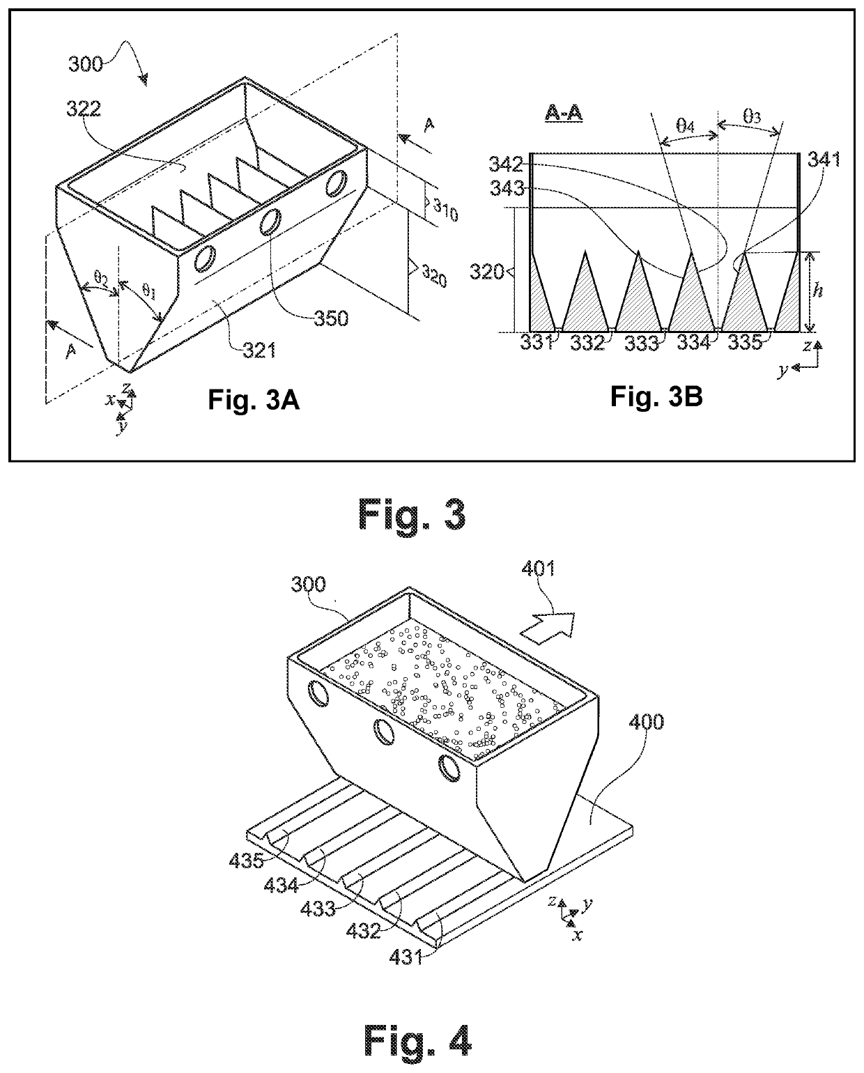
[0071]FIG. 3A, according to an exemplary embodiment, the hopper (300) of the device of the invention is generally wedged shaped and comprises a top portion (310) and a bottom portion (320) so-called discharge portion, comprising two inclined walls (321, 322) converging towards the bottom openings of the hopper, said openings being distributed in a transverse direction (y).

[0072]The hopper (300) comprises, in its top portion, means for fixing it in an additive manufacturing machine, in particular by bolting and in particular to a carriage, the motion speed of which is controlled.

[0073]According to this exemplary embodiment, the two inclined walls (321, 322) of the bottom portion (320) of the hopper are symmetrically inclined facing a transverse vertical plane (x, y), by an angle θ1=θ2.

[0074]Alternatively, the two walls are inclined according to angles (θ1, θ2), different relative to the transverse vertical plane. The tilt angle (θ1, θ2) of a wall being counted between 0°, for a verti...


PUM

PropertyMeasurementUnit
friction coefficientaaaaaaaaaa
volumeaaaaaaaaaa
angleaaaaaaaaaa

Abstract

A device for depositing a layer of granular material on a deposition surface. The device includes a discharge hopper, a scraper, and a transporter to move the discharge hopper and the scraper relative to the deposition surface. The hopper includes a plurality of discharge holes, aligned in a transverse direction, a top portion and a conical bottom discharge portion. The bottom discharge portion includes two transverse walls that are inclined towards the discharge holes. Each compartment, of a transverse compartmentalization of the discharge portion, includes two walls perpendicular to the transverse walls of the conical bottom discharge portion and inclined towards the discharge holes. Each compartment facing a discharge hole forms a pyramid-shaped conduit in the bottom discharge portion. The consecutive walls of the two compartments being joined at a corner where they meet in the bottom discharge portion.

Description

TECHNICAL FIELD[0001]The invention pertains a device and a method for depositing a granular material for additive manufacturing. The invention is adapted to the implementation of an additive manufacturing method using selective sintering, selective melting or selective spraying of binder on a granular material bed, the granular material being a polymer powder, a metal powder, a sand or a ceramic powder.BACKGROUND OF THE INVENTION[0002]These additive manufacturing methods consist in their principle of selectively agglomerating, by melting, sintering or spraying a binder, the grains of a granular material in a layer of defined thickness, deposited on a layer of granular material having previously been subject to the same selective agglomeration process. The term “agglomeration” is here considered in a broad sense, the different considered methods producing very different natures of bonds between the grains subjected to the selective effect.[0003]The selectively agglomerated portion of...

Claims


Application Information

Patent Timeline
Patent Type & Authority Applications(United States)
IPC IPC(8): B29C64/329B29C64/236B29C64/214B33Y40/00B33Y30/00B33Y10/00
CPCB29C64/329B29C64/236B29C64/214B33Y40/00B33Y30/00B33Y10/00B29C64/153B29C64/165B29C64/209B29C64/255Y02P10/25B22F12/52B22F12/67B22F10/28
Inventor HASCOËT, JEAN-YVESMOGNOL, PASCALLE NÉEL, TUGDUAL
Owner ECOLE CENTE DE NANTES
Learn More