
Induction heating roller apparatus, fixing apparatus and image formation apparatus

a technology of fixing apparatus and heating roller, which is applied in the direction of electric/magnetic/electromagnetic heating, instruments, electrographic processes, etc., can solve the problems of inefficient heat source of halogen lamps, large amount of power, and large heat capacity, and achieves relatively large coil pitch, high magnetic coupling, and increased heating roller temperature

Inactive Publication Date: 2005-02-01
HARISON TOSHIBA LIGHTING CORP
View PDF15 Cites 19 Cited by
  • Summary
  • Abstract
  • Description
  • Claims
  • Application Information

AI Technical Summary

Benefits of technology

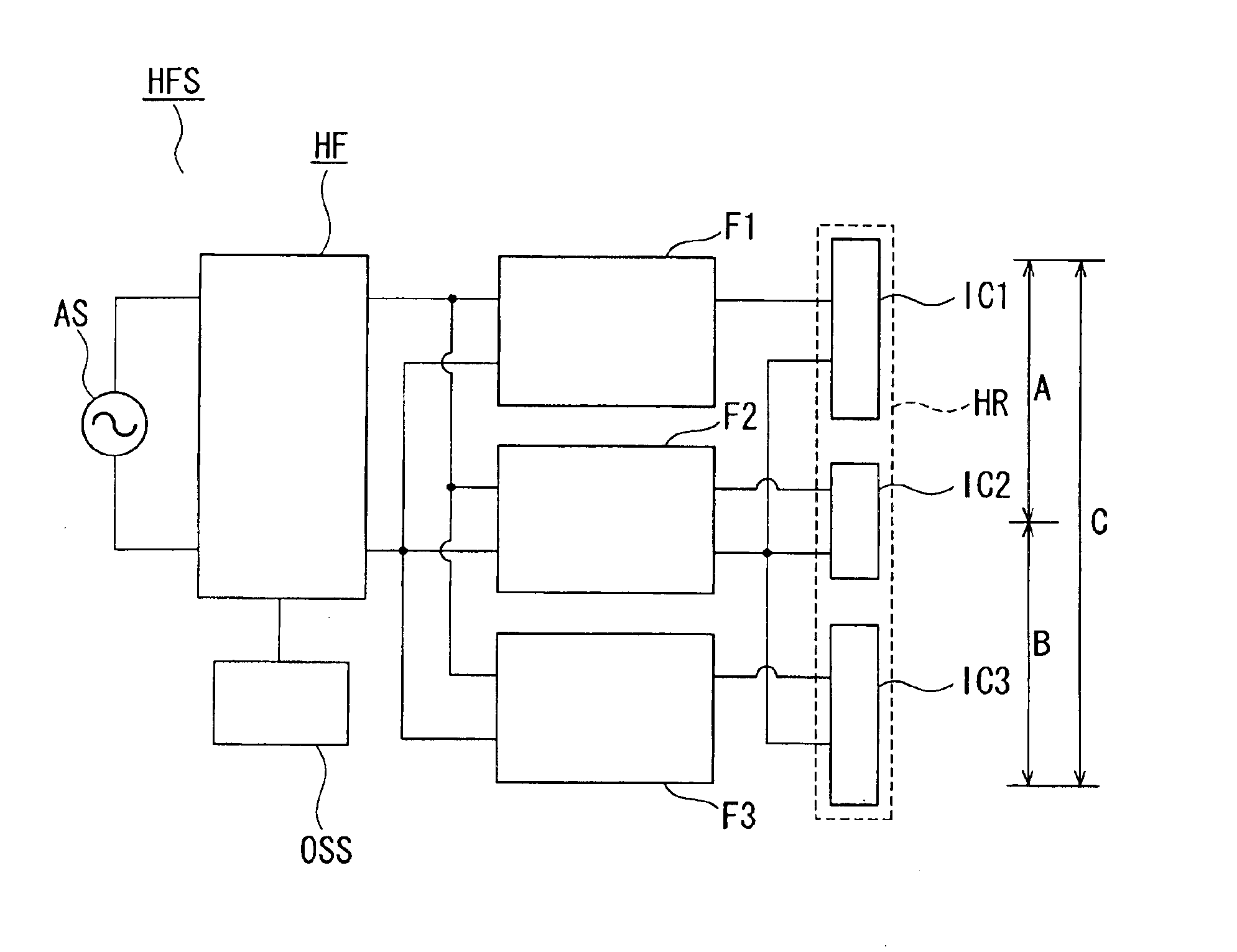
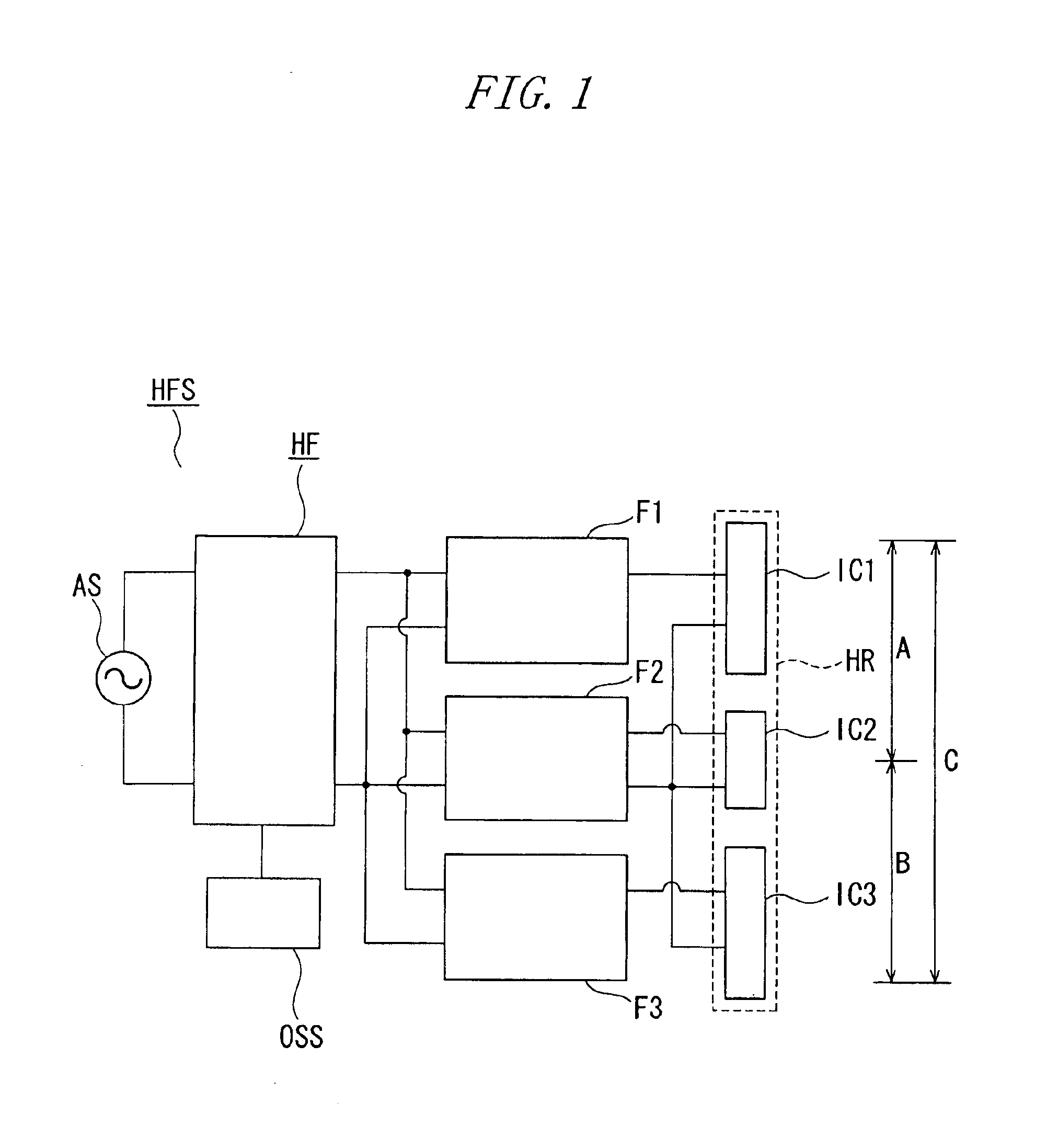
According to a first preferable embodiment of the present invention, the second induction coil is placed between the first induction coils opposed to the adjacent heating areas of the heating roller.
According to the first embodiment, the outer face of the induction coil is even due to the above configuration. For this reason, it is possible to obtain a high magnetic coupling by approximating the induction coil to the heating roller.
According to a second preferable embodiment of the present invention, the second induction coil is placed with its both ends overlapping the first induction coils opposed to the adjacent heating areas of the heating roller.
And according to the second embodiment, it becomes even easier, by the above configuration, to equalize the temperature distribution in the heating areas of the heating roller opposed to the first and second induction coils.
As the first and second induction coils are overlapping at both ends, it is possible to render a coil pitch relatively larger so that the magnetic field of the portion will not become too strong to excessively increase the temperature of the heating roller.
Furthermore, as the portion for intervening between each induction coil and the frequency-variable high frequency power supply and controlling the high frequency power supplied to the induction coil is comprised of the filter means, it is possible, without being influenced by the configuration of the induction coils, to exert stable control.

Problems solved by technology

However, the halogen lamp heat sources are inefficient and require a large amount of power.
Further, the heat capacity is much smaller than that of the eddy current loss technique.

Method used


Image

  • Induction heating roller apparatus, fixing apparatus and image formation apparatus
  • Induction heating roller apparatus, fixing apparatus and image formation apparatus
  • Induction heating roller apparatus, fixing apparatus and image formation apparatus

Examples


first embodiment

the outer face of the induction coil is even due to the above configuration. For this reason, it is possible to obtain a high magnetic coupling by approximating the induction coil to the heating roller.

According to a second preferable embodiment of the present invention, the second induction coil is placed with its both ends overlapping the first induction coils opposed to the adjacent heating areas of the heating roller.

second embodiment

And it becomes even easier, by the above configuration, to equalize the temperature distribution in the heating areas of the heating roller opposed to the first and second induction coils.

As the first and second induction coils are overlapping at both ends, it is possible to render a coil pitch relatively larger so that the magnetic field of the portion will not become too strong to excessively increase the temperature of the heating roller.

According to a third preferable embodiment of the present invention, the high frequency power supply is the frequency-variable high frequency power supply capable of feeding the power to a plurality of the first and second induction coils in common and having a variable output frequency, and the induction coil selection means is the filter means which intervenes between the frequency-variable high frequency power supply and the induction coils and controls the high frequency power which is passing by selectively operating according to the freque...

third embodiment

And the filter means intervenes between the plurality of induction coils and the frequency-variable high frequency power supply, and controls the high frequency power passing the filter means by selectively operating according to the frequencies. Therefore, it is possible, by changing the power supply frequency, to selectively energize a desired induction coil. For this reason, it is possible to switch the lengths of the heating areas of the heating roller as desired. In the case of using the induction coil apparatus for fixing the toner image on the image formation apparatus, it is possible to preferentially heat only the areas suited to the paper size when increasing the temperature of the heating roller. However, if the filter means is constituted to have the high frequency power simultaneously supplied to the plurality of induction coils and the frequency is selected so that a plurality of filter means become the pass bands respectively, it is possible to heat the induction coi...


PUM


Abstract

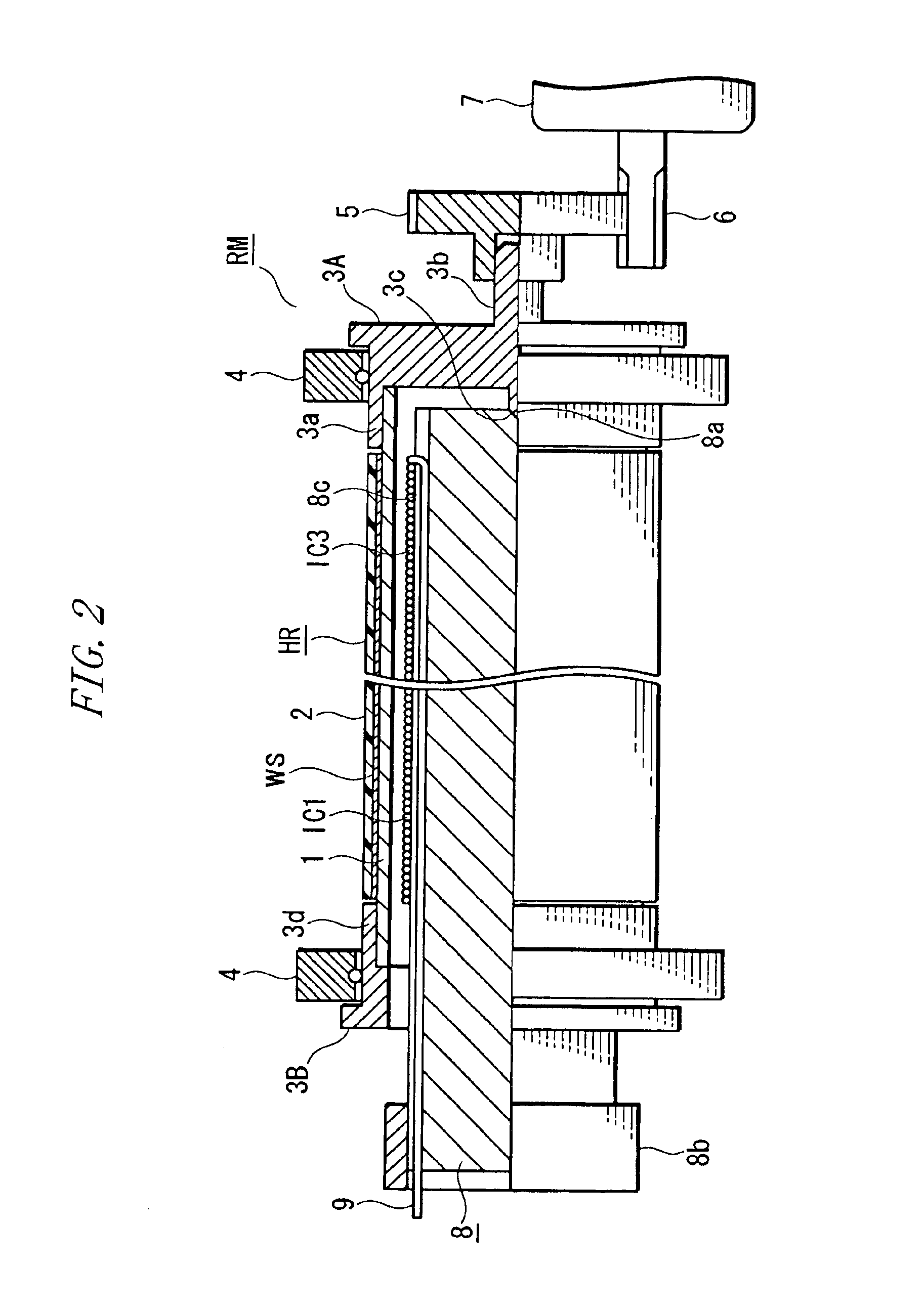
An induction heating roller apparatus has a heating roller capable of switching among a plurality of heating areas of different lengths according to a size of an object to be heated, a plurality of first induction coils opposed to a plurality of heating areas of the heating roller, and second induction coils placed opposite a part astride adjacent heating areas of the heating roller. A high frequency power supply provides high frequency power to the first and second induction coils. High frequency output is selectively supplied to the first induction coils and the second induction coils.

Description

BACKGROUND OF THE INVENTION1. Field of the InventionThe present invention relates to an induction heating roller apparatus and to a fixing apparatus and an image formation apparatus, which are provided with the fixing apparatus.2. Description of the Prior ArtHeating rollers, which employ halogen lamps as heat sources, are used in the prior art to thermally fix a toner image. However, the halogen lamp heat sources are inefficient and require a large amount of power. Accordingly, a technique involving induction heating is being developed to solve such problems.Japanese Patent Laid-Open No. 2000-215974 describes an exciting coil, which is arranged near a heated object. The exciting coil generates an induction current in the heated object, which is a magnetic heating roller. The exciting coil is formed by winding a coil in a planar manner along a curved surface of the heated object. A magnetic core is arranged along the curved surface or the exciting coil on the side opposite to the hea...

Claims


Application Information

Patent Timeline
Patent Type & Authority Patents(United States)
IPC IPC(8): G03G15/20
CPCG03G15/2042G03G15/2053
Inventor YOKOZEKI, ICHIROOGASAWARA, TAKAYUKITANAKA, TAKAAKISUZUKI, TOSHIYA
Owner HARISON TOSHIBA LIGHTING CORP
Learn More