Wire winding device for a high power level transformer

a transformer and high-power technology, applied in transformers/inductances, magnets, magnetic bodies, etc., can solve the problems of reduced reliability, special challenges of the paradigm, and the bulky rotor of the rotor, so as to facilitate heat dissipation, increase the magnetic coupling between the stator and the rotor, and improve the effect of heat conduction efficiency

Inactive Publication Date: 2010-10-05
SCHLEIFRING MEDICAL SYST USA
View PDF7 Cites 1 Cited by
  • Summary
  • Abstract
  • Description
  • Claims
  • Application Information

AI Technical Summary

Benefits of technology

[0012]Another object of the present invention is to provide a more efficient means of winding wire for rotary transformers for use in wind and water turbines, equipment, and other contact-less power transmission applications such as computer aided tomography (CAT). A feature of the present invention is a wire-holder device facilitating the encapsulation of the transformer windings with high thermal conductivity resin effective up to 500° F. An advantage of the present invention is that high power output but low-mass / low-moment-of-inertia rotors can be manufactured to accommodate rotor rotation rates in the thousands of revolutions per minute (rpm). Typical rotation rates for applications where the present invention can be put into effect include 10-300 rpm for wind turbines, 1000 rpm for jet-engine turbines and up to 20,000-30,000 rpm for high speed drills.
[0013]Still another object of the present invention is to provide a rotary transformer with increased magnetic coupling between stator and rotor. A feature of this invention is a plurality of ferrite and non-ferrite channel-ways or wire-holders removably received in annular grooves defined by opposing surfaces of the stator and rotor. The channel-ways are adapted to frictionally receive winding wire. An advantage of this invention is that the surface area of each of the channel ways facilitates heat dissipation from windings passing through the channel ways.
[0014]Another object of the present invention is to provide a rotary transformer which can accommodate power loads in excess of 1000 kilowatts by optimizing heat transfer from windings passing through a plurality of channel ways. A feature of this invention is that the channel ways are removably received in an annular groove formed in a foundation substrate of a rotor and stator, and each of the channel ways defines a chord of the arc formed by the annular grooves. An advantage of this feature is more efficient heat conduction away from each of the channel ways and therefore the windings. Another advantage of this feature is a reduction in magnetic leakage.
[0015]In brief, the present invention provides a wire-holding device for winding a transformer that facilitates the winding of single-layer resin-encapsulated stator and rotor windings. The invented transformer can accommodate power levels up to 1 megaWatt and operate typically in the 1 kW to 400 kW range. The invented rotary transformer comprises: a stationary member comprising a first mechanical carrier with first windings thereupon; a rotary member comprising a second mechanical carrier with second windings thereupon, said rotary member in registration with said stationary member; segmented highly permeable magnetic material ingots disposed circumferentially on said carriers so as to form channels adapted to receive said windings whereby said first and second windings and said magnetic material are affixed to said mechanical carriers with a high thermal conductivity resin; and wire-holders interspersed among these ingots, said wire-holders designed to frictionally engage, and therefore maintain the position of, single wires in said windings, each wire-holder manufactured from a magnetic material ingot defining a plurality of grooves with each groove dimensioned to snugly receive a single strand of wire and further defining a ridge between grooves not higher than half the diameter of the wire.
[0016]Also, the present invention provides a method for winding rotary transformer comprising: providing a stationary member comprising a first mechanical carrier adapted to receive first windings thereupon; providing a rotary member comprising a second mechanical carrier adapted to receive second windings thereupon and providing means to place said rotary member in registration with said stationary member; providing segmented highly permeable magnetic material ingots disposed circumferentially on said carriers so as to form channels adapted to receive said windings; and providing wire-holders interspersed among these ingots, said wire-holders frictionally engaging single wires in said windings.

Problems solved by technology

This paradigm presents special challenges.
First, both the stator and especially the rotor must be small in bulk.
Secondly, it is imperative that the rotary transformer be able to withstand extreme weather conditions.
These are prone to reduced reliability, frequent maintenance problems, and the generation of electrical noise that can interfere with, or damage, sensitive electronics.
Oxidation and environmental agents, such as water, ice, and dust, have adverse effects on brush / slip-ring power transmission.
Replacing brush / slip-ring mechanisms with contactless configurations often ameliorate some of the problems associated with operations in environmentally-harsh situations.
However, a problem inherent with contactless systems is the generation of high temperatures within the windings.
This ultimately leads to reduced power output and eventually, damage to the transformer.
A problem with current winding configurations is that wire, when first placed into the grooves of carriers, tend not to stay in place.
Specifically, once a wire is unwound from a supply spool and placed in a winding groove, the wire strands do not conform to the smooth curved arcs defined by state of the art winding carriers.
Nor can the wire be consistently positioned to contact the carrier.
Narrowing the winding groove does not always lead to a satisfactory arrangement inasmuch as two wires may come in contact with each other in several places.
This would lead to local heat build up and electronic interference.
Configuring wire ways to accept only one wire is costly and inefficient, particularly if a high number of windings is desired.
Moreover, single-wire wire ways do not provide adequate flexibility when one is laying stiff wires such as the ones one often encounters in rotary transformers.

Method used


Image

  • Wire winding device for a high power level transformer
  • Wire winding device for a high power level transformer
  • Wire winding device for a high power level transformer

Examples


Embodiment Construction

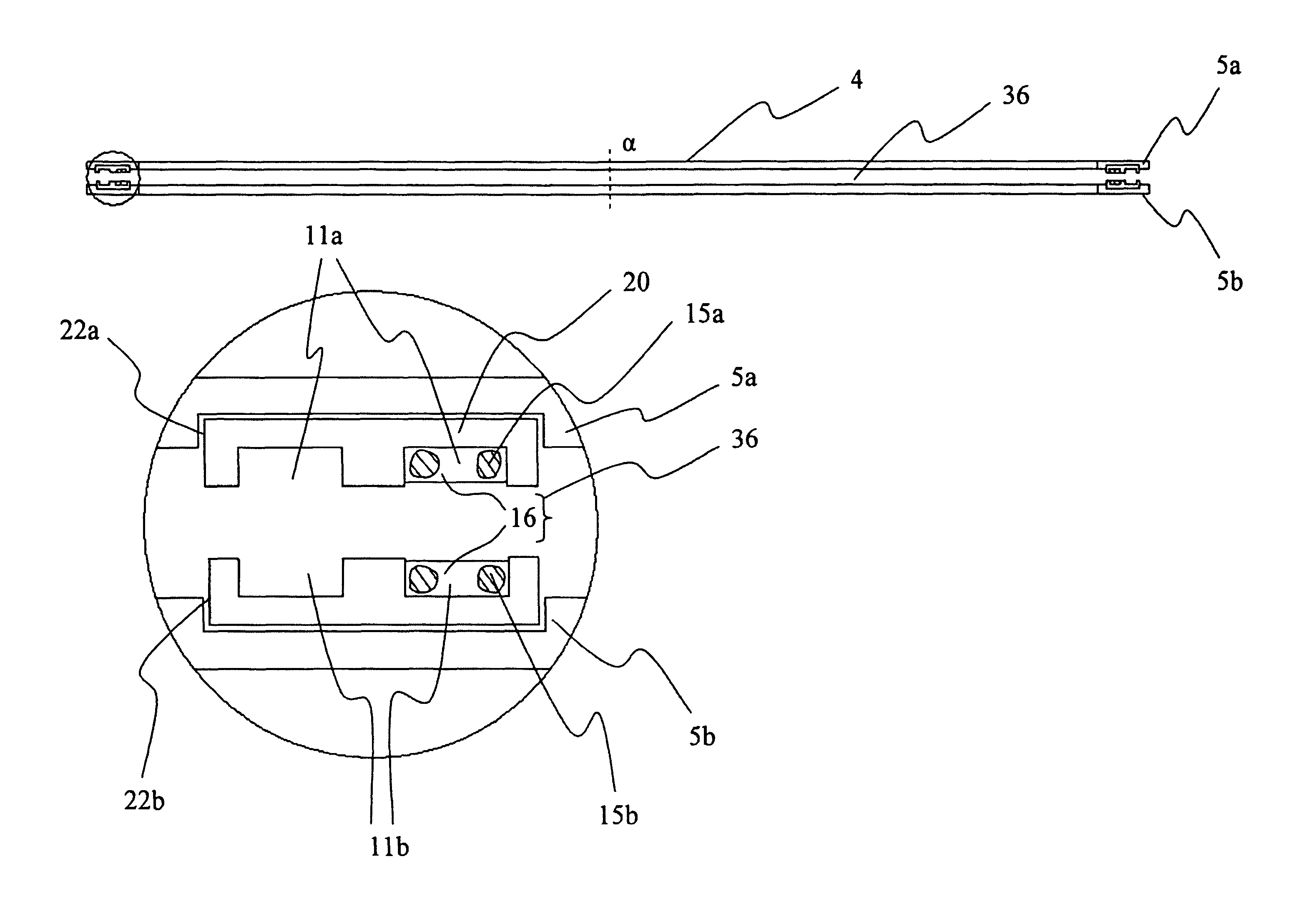
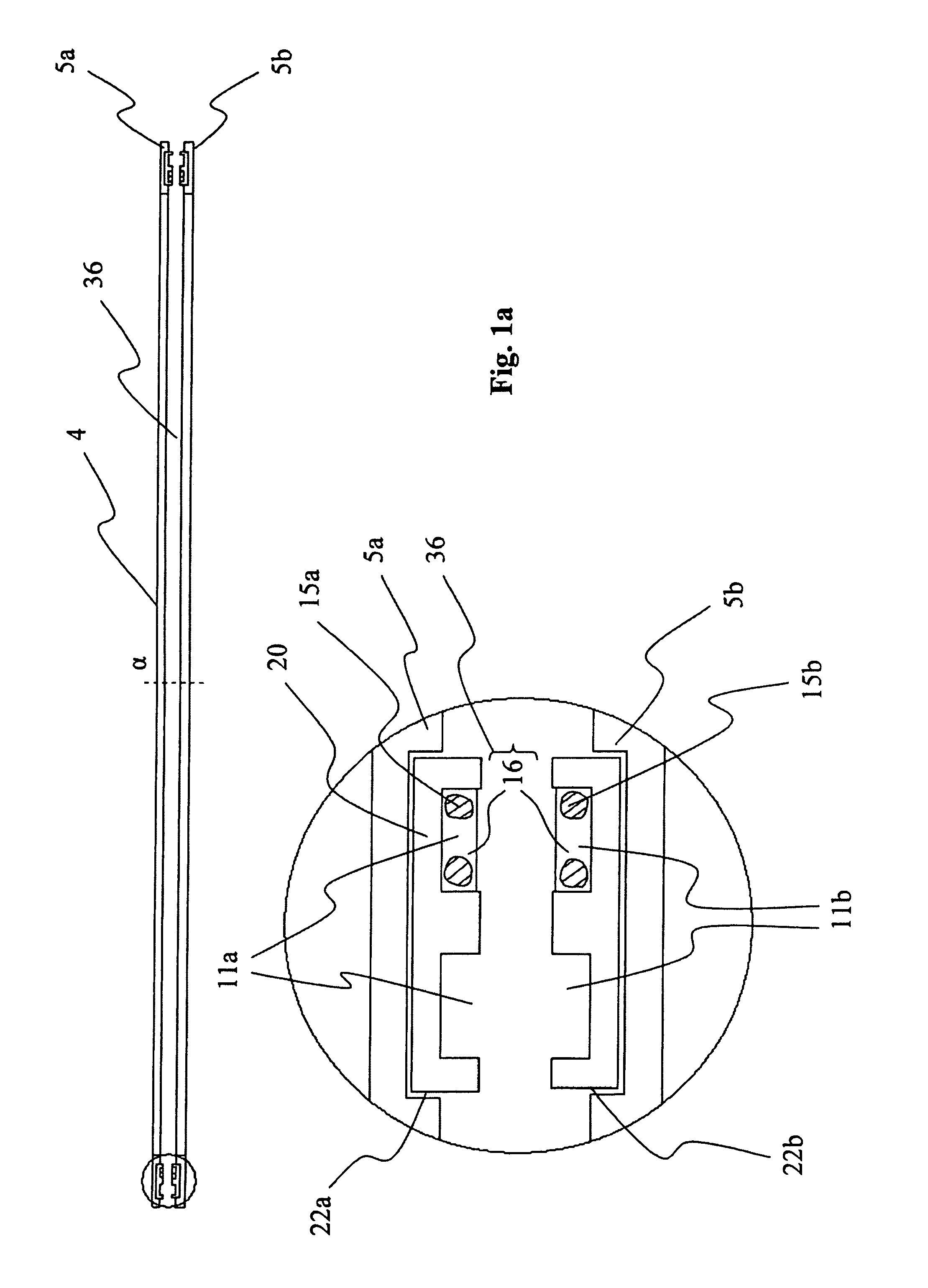
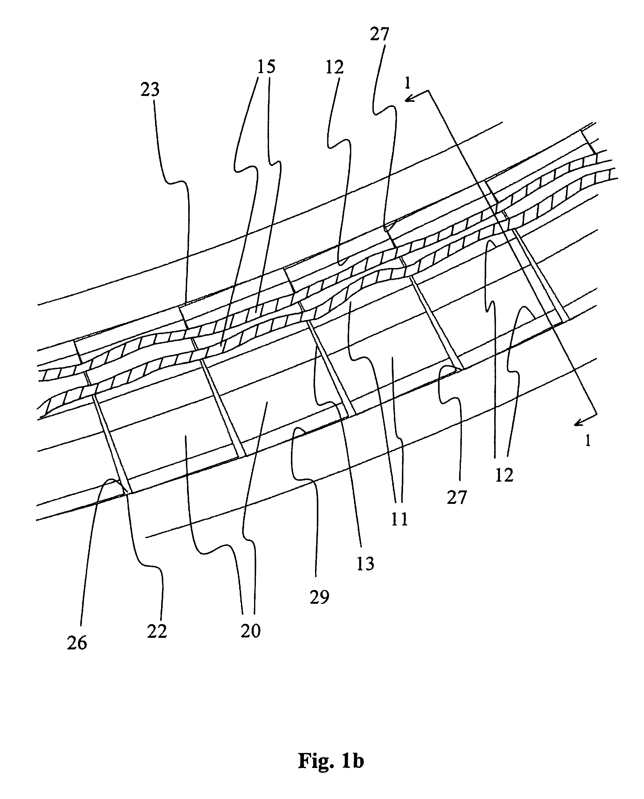
[0026]The present invention provides a device and a method to be used in winding rotary transformers employed in conjunction with high power (more than 1,000 kW) electric generation and transmission, including applications involving the use of stationary or rotary transformers where power must be transferred to or from a stationary or a mobile platform (e.g. high-power transformers, motors, generators, turbines, CAT-scan devices, etc. . . . ) Typically, such transformers operate at frequencies in the 500 kHz range and utilize Litz wire. The invented device comprises a wire-holder for single strands of wire that holds such wires taut, at a constant separation but in close proximity to each other so as to facilitate the winding of wire in a “pancake-type” rotary transformer. One embodiment of the invented wire-holder comprises a generally flat ingot made from magnetic material. The ingot defines a plurality of grooves or trough, with each trough dimensioned to snugly receive a single ...


PUM

PropertyMeasurementUnit
poweraaaaaaaaaa
frequenciesaaaaaaaaaa
temperaturesaaaaaaaaaa

Abstract

Wire-holders are provided that confine a single wire over a limited arc section and that are interspersed with ferrite ingots that provide wire-ways for several wires are utilized in the winding of the coils of a transformer. A method for consistently producing windings having accurate wire placement on rotors, stators, and other electrical componentry is also provided.

Description

BACKGROUND OF THE INVENTION[0001]1. Field of the Invention[0002]This invention relates to an improvement in winding transformers, and more particularly, this invention relates to an improvement in the process of winding rotary transformers featuring bi-directional high level power transmission.[0003]2. Background of the Invention[0004]Windmills, wind turbines, and other wind-actuated power devices may utilize a rotary transformer that comprises one or more rotors and stators positioned at the top of a mast or tower. This paradigm presents special challenges. First, both the stator and especially the rotor must be small in bulk. Also, the rotor rotates at a high rate around a horizontal axis. Yet the windings of both the stator and the rotor must be able to carry large currents; thus it is imperative that effective cooling be provided thereto. Secondly, it is imperative that the rotary transformer be able to withstand extreme weather conditions.[0005]State of the art wind turbine sys...

Claims


Application Information

Patent Timeline
Patent Type & Authority Patents(United States)
IPC IPC(8): H01F21/04H01F27/24H01F27/28
CPCH01F27/325H01F38/18Y10T29/49071Y10T29/49009
Inventor DUNLAP, GREGORY M.CHAN, KAI CHI
Owner SCHLEIFRING MEDICAL SYST USA
Why Eureka
Try Eureka