
Method and system for measuring in patterned structures

a technology of patterned structures and methods, applied in the field of optical measurement techniques, can solve problems such as ineffective ocd techniques

Active Publication Date: 2012-03-27
NOVA MEASURING INSTR LTD
View PDF1 Cites 22 Cited by
  • Summary
  • Abstract
  • Description
  • Claims
  • Application Information

AI Technical Summary

Benefits of technology

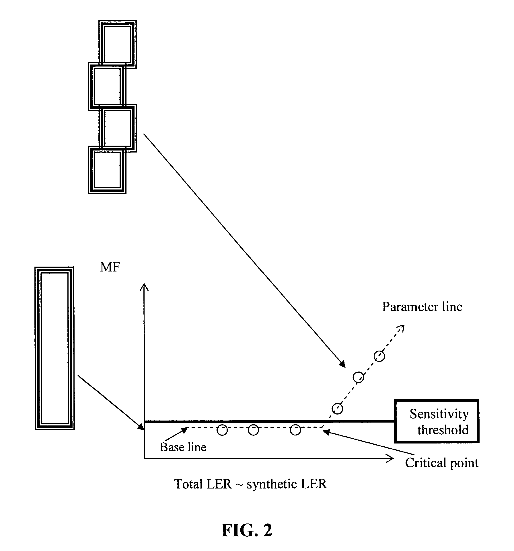
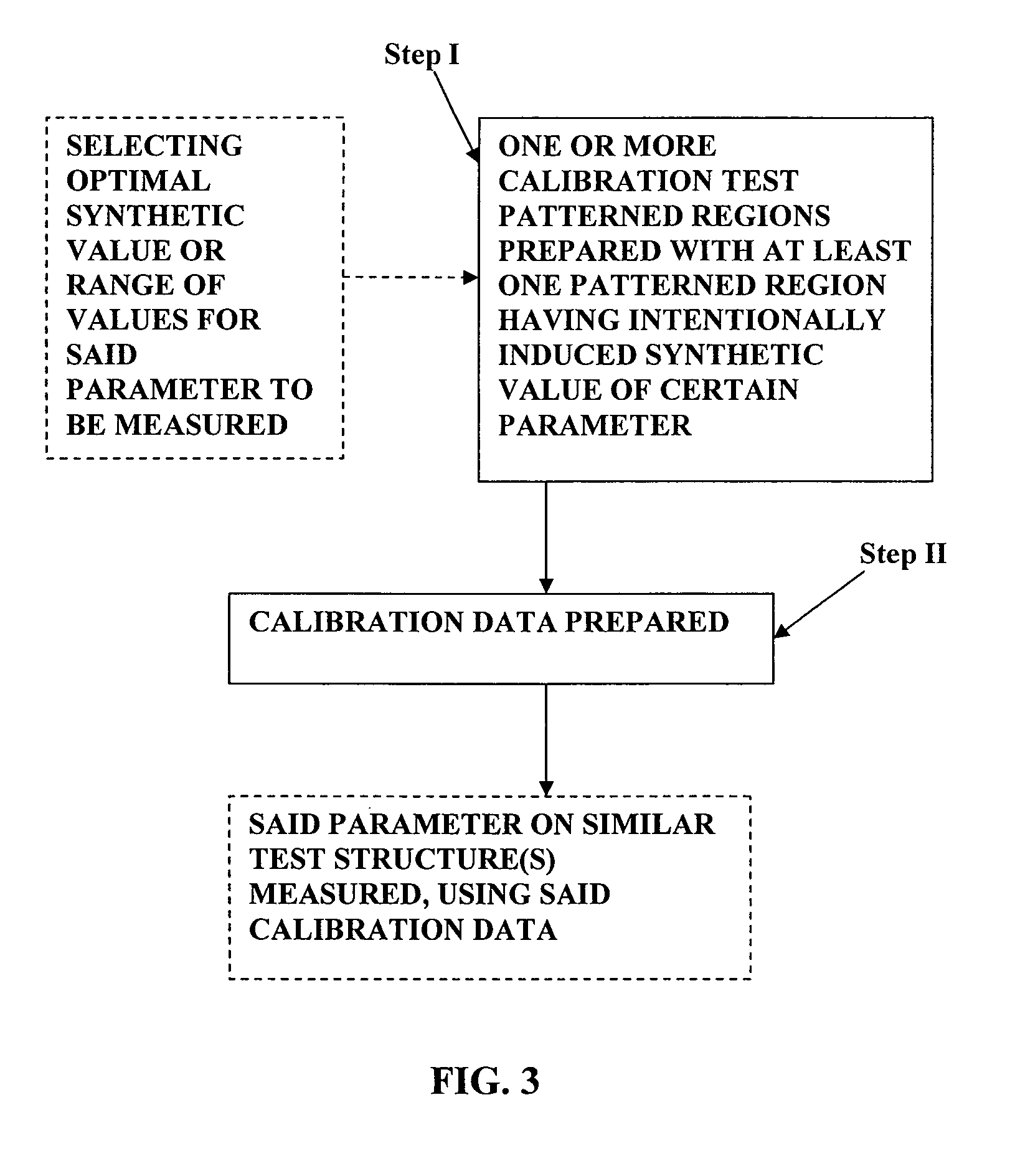
[0008]The present invention solves the weak parameter problem by providing a novel technique enabling use of the principles of OCD metrology (or Scatterometry) for measuring various parameters of the structure. The technique of the present invention consists of providing at least one test structure (typically within a test site of an article / structure to be measured) having a patterned feature configured with an enhanced effect of the respective parameter.
[0009]Preferably, a plurality of pre-designed test structures are provided with different intentionally introduced effects of a certain parameter. Generally speaking, the present invention provides for amplifying the sensitivity of an optical measurement system to specific “weak” parameter(s), which would otherwise be non-detectable and / or non-model-able by the measurement technique with a desired accuracy. More specifically, the invention provides for enhancing the optical response of a certain feature of the structure by a predetermined value, to thereby increase the signal-to-noise of to measurements for this specific parameter.
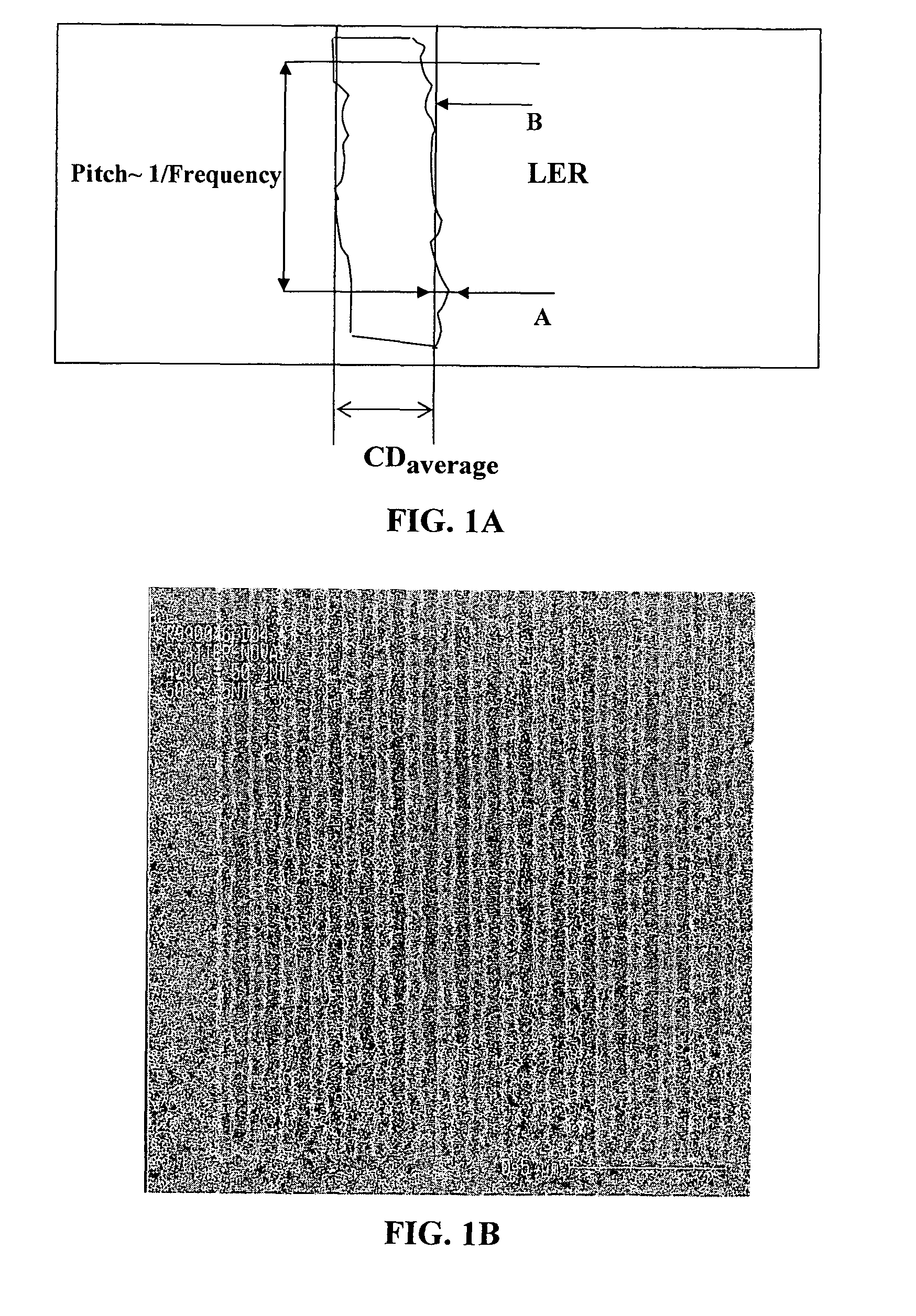
[0010]Considering for example such a parameter or feature as Line Edge Roughness (LER), which is a parameter that might affect dopant concentration profiles or off-state leakage currents and drive currents, the present invention enhances the LER effect by intentionally introducing a predetermined profile of roughness into a line edge while manufacturing a test structure with a lithography tool (e.g. imprinting technique). The introduced profile of roughness is such that a total signal, resulting from this intentionally introduced line edge roughness and line edge roughness affected by a patterning process, becomes higher than a threshold defined by a signal-to-noise ratio of the measurement system.
[0013]Thus, according to one broad aspect of the invention, there is provided a sample having a patterned area and comprising at least one test structure having a patterned region similar to a pattern in said patterned area, the patterns in the patterned area and in said at least test structure being produced by the same patterning process, wherein said at least one test structure comprises at least one pattern parameter of a predetermined value intentionally increased above a natural value of said certain parameter induced by a patterning process, thereby enabling determination of the natural value of said certain parameter induced by said patterning process.

Problems solved by technology

As for the weak effects, such as for example LER (Line Edge Roughness), the OCD techniques might not be effective.
A problem with using OCD for measurement of some weak parameters of a patterned structure, such as LER, is also associated with the fact that typical wavelengths that OCD tools are using today are above 200 nm while the basic need for measurement of such random phenomena on the side walls as LER is 2 orders of magnitude lower.

Method used


Image

  • Method and system for measuring in patterned structures
  • Method and system for measuring in patterned structures
  • Method and system for measuring in patterned structures

Examples


Embodiment Construction

[0053]As indicated above, according to the conventional techniques for measuring in patterned structures based on OCD measurement technique, a fitting procedure is usually employed, whereby a theoretical model describing a structure under measurements is used to generate a theoretical signal, and this signal is iteratively compared to the measured signal, while varying the model parameters, or a library is used or a combination of both. According to this technique, a merit function is typically determined and compared to a certain predefined threshold. However, if a parameter of the structure has no detectable effect on the signal and / or cannot be modeled, the merit function cannot be used to determine the value of the parameter.

[0054]The present invention provides an alternative approach enabling determination of a variation of the merit function with the variation of the respective parameter using one or more test structures, where at least one of them has an intentionally induced...


PUM

PropertyMeasurementUnit
wavelengthsaaaaaaaaaa
edge roughnessaaaaaaaaaa
roughnessaaaaaaaaaa

Abstract

A sample having a patterned area and a method for use in controlling a pattern parameter is presented. The sample comprises at least one test structure having a patterned region similar to a pattern in the patterned area, the patterns in the patterned area and in the at least test structure being produced by the same patterning process. The at least one test structure comprises at least one pattern parameter of a predetermined value intentionally increased above a natural value of said certain parameter induced by a patterning process. By this, the natural value of the parameter induced by the patterning process can be determined.

Description

CROSS-REFERENCE TO RELATED APPLICATIONS[0001]This application is a U.S. National Phase Application under 35 U.S.C. 371 of PCT International Application No. PCT / IL2008 / 000172 which has an international filing date of Feb. 7, 2008, and which claims priority from Israel Patent Application No. 181,209, filed Feb. 7, 2007, all of which disclosures are hereby incorporated by reference.FIELD OF THE INVENTION[0002]This invention is in the field of optical measurement techniques, and relates to a method and system for measuring parameters of a structure, particularly useful for patterned structures such as integrated circuits, e.g. for controlling a patterning process (e.g. lithography).BACKGROUND OF THE INVENTION[0003]In the semiconductor industry, one of the important procedures of advanced process control is control of geometrical dimensions of a structure being processed. Such measurements can be carried out by an AFM or CDSEM metrology tool. These are stand alone, bulky tools, the measu...

Claims


Application Information

Patent Timeline
Patent Type & Authority Patents(United States)
IPC IPC(8): G03F9/00G01B11/30G01B11/00G03F1/00G03F1/44
CPCG01B11/303G03F1/14G03F1/44G03F7/70683G03F7/70516G03F7/70625G03F7/70433
Inventor YOEL, COHEN
Owner NOVA MEASURING INSTR LTD
Learn More