System and method for thermally coupling memory devices to a memory controller in a computer memory board

a memory controller and memory device technology, applied in the field of computer systems, can solve the problems of memory device and controller operating independently, and the timing window specified by the designer will tend to shift away from the optimum design intent, and achieve the effect of eliminating memory timing problems

Active Publication Date: 2015-11-26
SRC COMP
View PDF2 Cites 4 Cited by
  • Summary
  • Abstract
  • Description
  • Claims
  • Application Information

AI Technical Summary

Benefits of technology

This patent is about a system and method that helps keep computer chip memory devices at a uniform temperature, which prevents timing issues. Traditionally, cooling methods cause the memory to shift timing as the temperature changes. However, by joining all the memory components together, this system ensures that the timing window tracks uniformly, resulting in improved performance.

Problems solved by technology

The problem with this conventional approach is that the memory devices and controller will operate independently at differing temperatures as the operating temperature of the computer memory board fluctuates.
As such, the timing window specified by the designer will tend to shift away from its optimum design intent, due to the relatively large temperature difference of each of the devices.

Method used


Image

  • System and method for thermally coupling memory devices to a memory controller in a computer memory board
  • System and method for thermally coupling memory devices to a memory controller in a computer memory board
  • System and method for thermally coupling memory devices to a memory controller in a computer memory board

Examples


Embodiment Construction

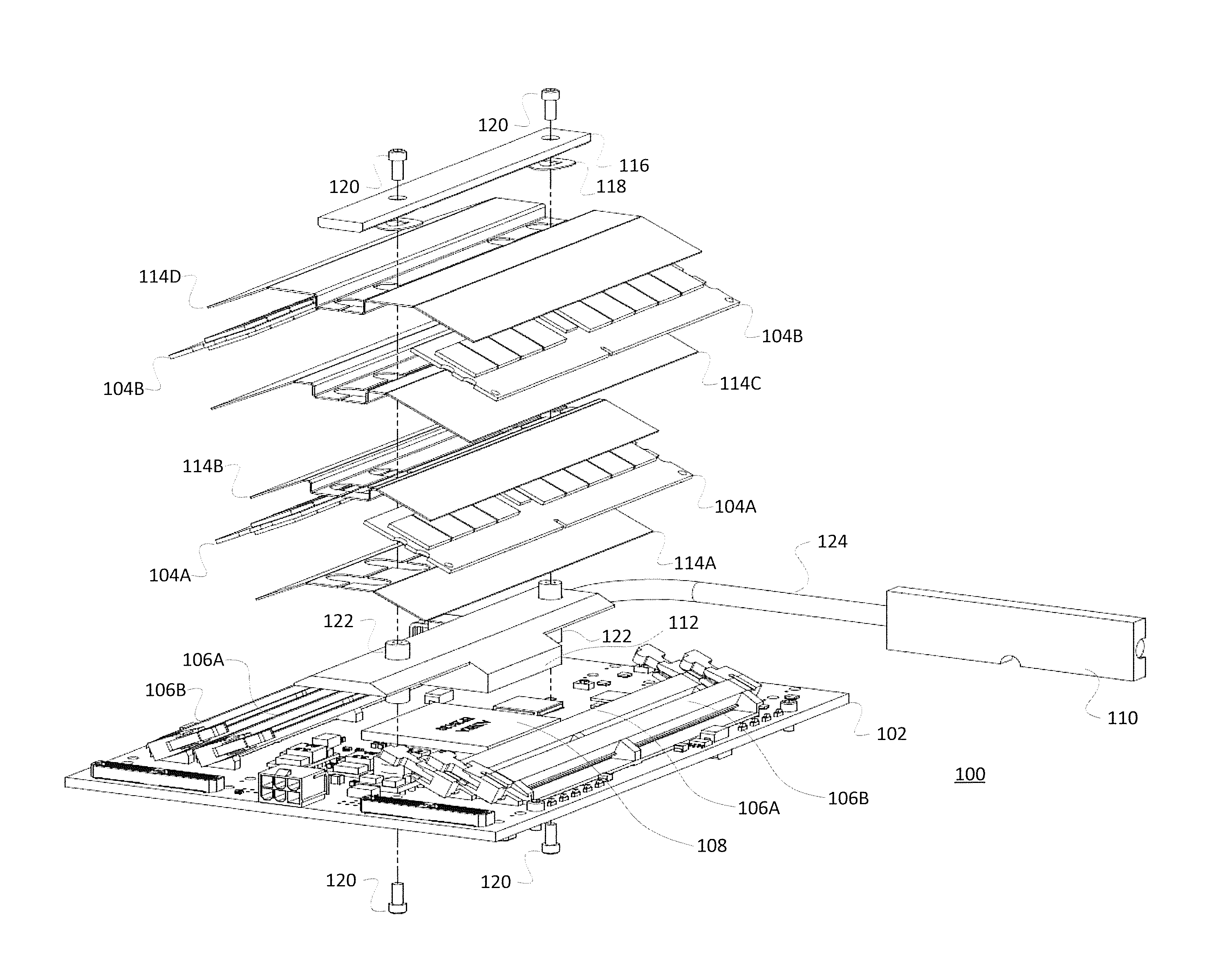
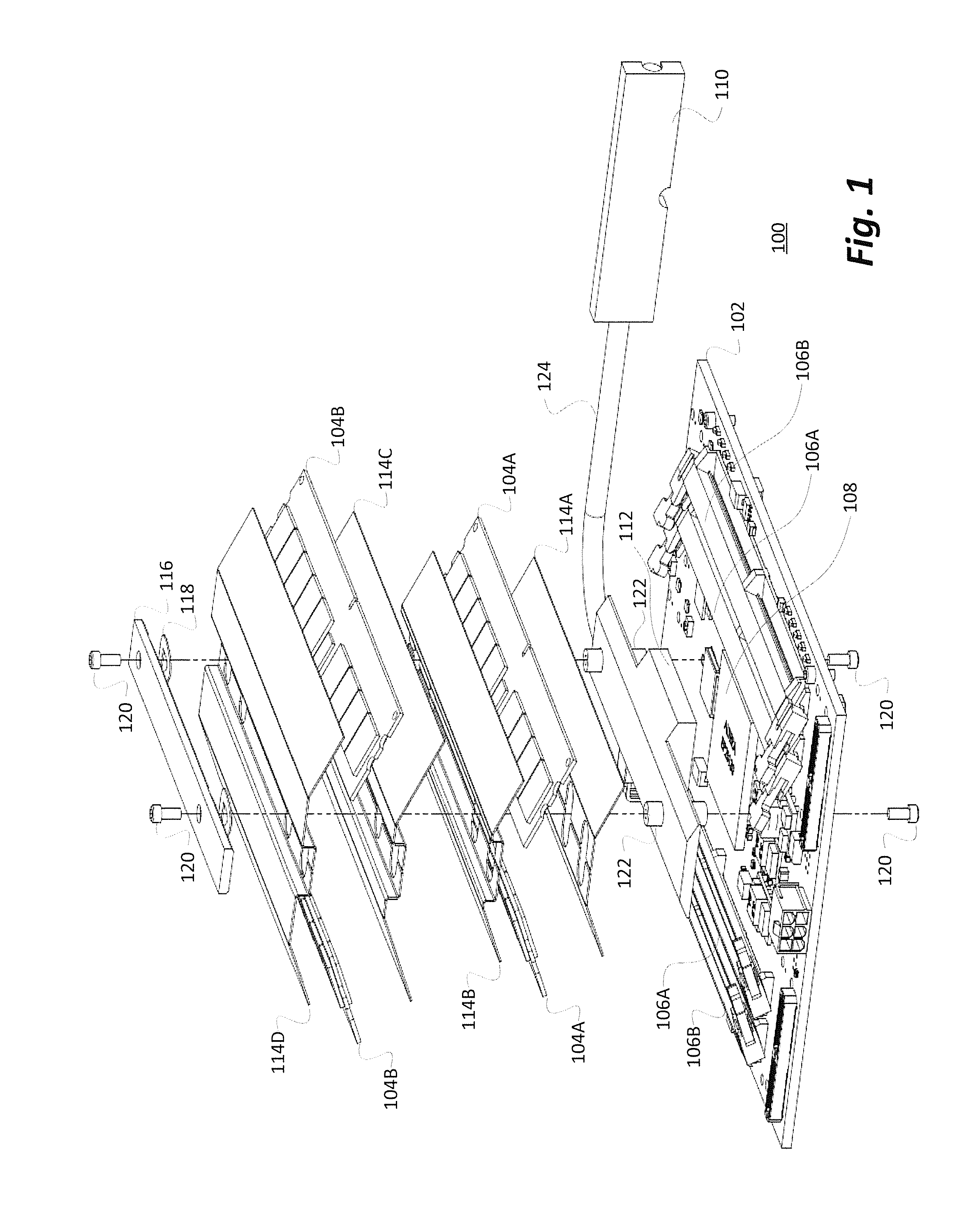
[0017]With reference now to FIG. 1, an exploded, isometric view of a representative embodiment of the system and method of the present invention for thermally coupling memory devices to a memory controller is shown. An exemplary computer memory board 100 comprises, in pertinent part, a circuit board 102 upon which are mounted a memory controller 108 associated with a number of memory modules 104A (left and right inner banks) and 104B (left and right outer banks) which are retained in corresponding left and right memory module sockets 106A and 106B. In the embodiment illustrated, the sockets 106A and 106B are disposed laterally of the memory controller 108 and inclined toward it to bring the memory modules 104A and 104B in closer physical proximity thereto.

[0018]In the representative embodiment illustrated, the memory modules 104A and 104B may be dual in-line memory modules (DIMMs) although it should be noted that the principles of the present invention are likewise applicable to any...


PUM

PropertyMeasurementUnit
Thicknessaaaaaaaaaa
Thicknessaaaaaaaaaa
Temperatureaaaaaaaaaa

Abstract

A system and method for thermally coupling memory devices, such as DIMM memory modules, to an associated memory controller such that both are cooled together at the same relative temperature. By maintaining all of the devices at a much more uniform temperature, memory timing issues are effectively eliminated. In accordance with an exemplary embodiment, the controller chip is physically located between two or more banks of memory, and is positioned under an adjoining heat sink while the memory DIMMs are positioned laterally of the controller chip in angled DIMM slots and are coupled to the controller chip with respective heat spreaders.

Description

BACKGROUND OF THE INVENTION[0001]The present invention relates, in general, to the field of computer systems, including computer memory boards, memory modules, scalable servers and rack mounted systems. More particularly, the present invention relates to a system and method for thermally coupling memory devices to a memory controller in a computer memory board.[0002]Memory devices and their respective controllers must operate within a limited temperature range in order for the memory to meet necessary timing specifications. At present, many different techniques have been employed in an attempt to provide cooling methods for memory modules such as cooling fans, heat sinks, heat spreaders and the like. However, the memory and associated controller devices have heretofore always been cooled through the use of separate devices and techniques.[0003]The problem with this conventional approach is that the memory devices and controller will operate independently at differing temperatures as...

Claims


Application Information

Patent Timeline
IPC IPC(8): H05K7/20H05K3/30H05K7/14
CPCH05K7/20809H05K7/20836H05K7/1485H05K3/30H05K2201/10159G06F1/163G06F1/20Y10T29/49131H05K1/0203H05K7/2039
Inventor KOEPPEL, ALLAN JEFFREYCOWLES, DOUGLAS
Owner SRC COMP
Why Eureka
Try Eureka