
Semiconductor device and method of manufacturing the same

a technology of semiconductors and semiconductors, applied in the testing/measurement of individual semiconductor devices, semiconductor/solid-state devices, instruments, etc., can solve the problems of poor wettability of semiconductors, achieve reliable connection, reduce impact, and improve reliability

Active Publication Date: 2015-09-24
ABLIC INC
View PDF5 Cites 7 Cited by
  • Summary
  • Abstract
  • Description
  • Claims
  • Application Information

AI Technical Summary

Benefits of technology

The present invention provides a semiconductor device and a method of manufacturing it that improves the strength of its solder bonding to a substrate. This is achieved by forming a thick solder layer on all surfaces of the outer lead exposed from the device, which ensures a firm bond with the substrate. Additionally, the method helps prevent damage to the inner lead when the device is separated from its lead frame and maintains reliable connections with the wire electrically connected to the semiconductor element. This improves the reliability of the semiconductor device.

Problems solved by technology

Accordingly there is a problem in that the solder wettability is poor when the semiconductor device is mounted on the substrate.

Method used


Image

  • Semiconductor device and method of manufacturing the same
  • Semiconductor device and method of manufacturing the same
  • Semiconductor device and method of manufacturing the same

Examples


Embodiment Construction

[0024]Now, the present invention is described with reference to the drawings.

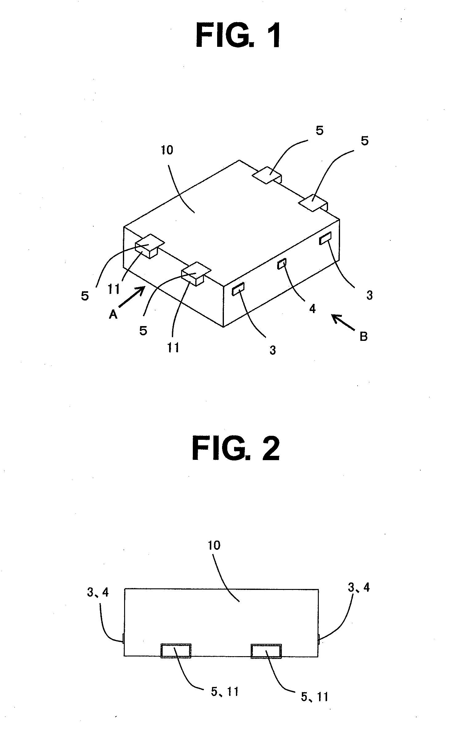
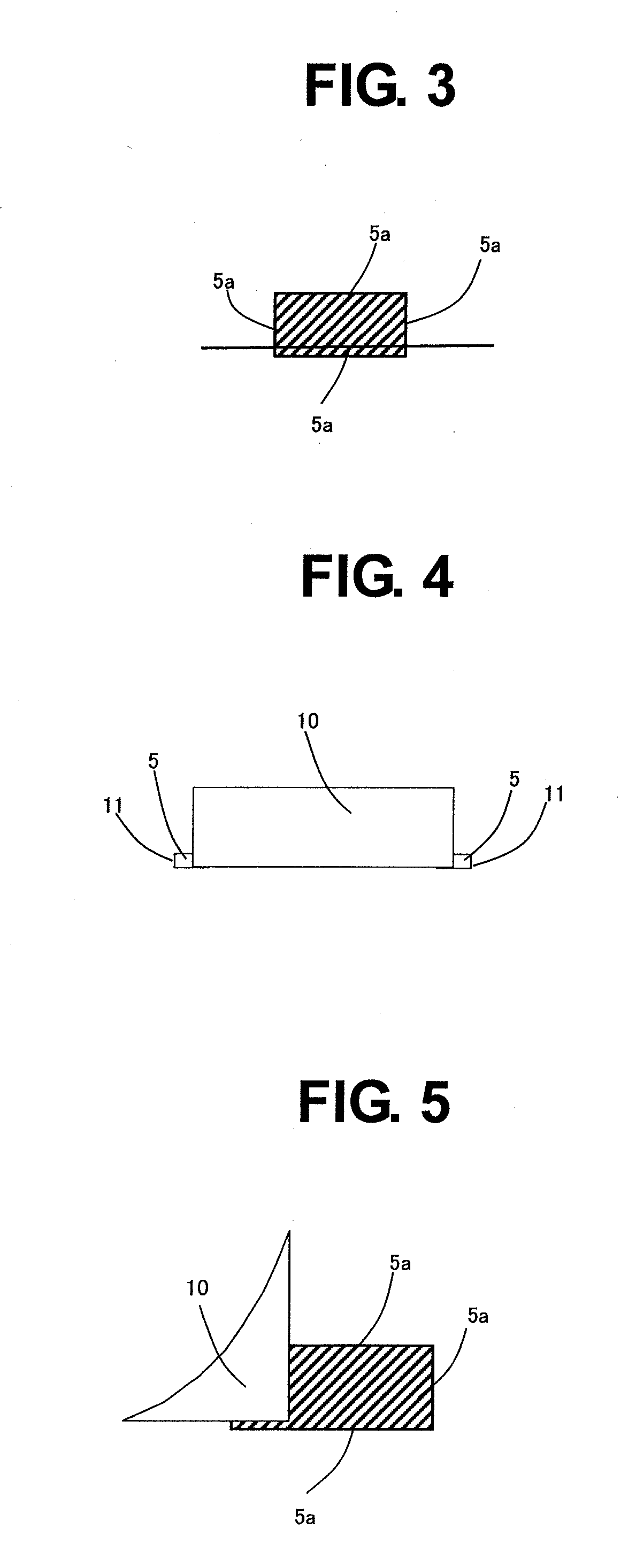
[0025]FIG. 1 is a bird's-eye view illustrating a semiconductor device according to an embodiment of the present invention, in which an outer lead 5 is illustrated on the upper side. The outer lead 5 has an upper surface (mounting surface), a side surface (outer lead cut surface), a surface opposite to the mounting surface, and surfaces each of which forms right angles with the mounting surface, the opposite surface, and the outer lead cut surface. The outer lead 5 extends from an encapsulating resin 10. Further, on a side surface of the substantially cuboid semiconductor device, inner lead suspension leads 3 and an island suspension lead 4 have been cut to expose the cut surfaces from the encapsulating resin 10.

[0026]FIG. 2 is a sectional view when viewed from the direction A of FIG. 1, in which the outer lead 5 is illustrated on the lower side and the lower surface of FIG. 2 corresponds to the mounting sur...


PUM


Abstract

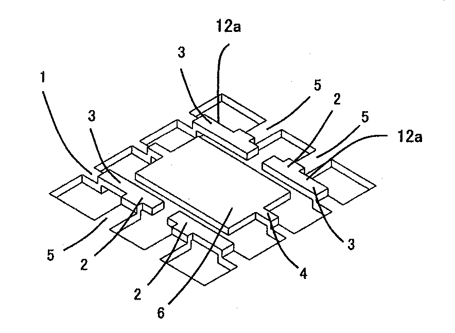
Provided is a semiconductor device using a lead frame, in which an outer lead (5) is electrically connected to an inner lead suspension lead (3) via an inner lead, and hence a plated film is also formed on an outer lead cut surface (11) so that a solder layer is easily formed on all of surfaces of the outer lead extending from an encapsulating resin (10). Further, the inner lead suspension lead (3) includes a first narrowed portion (12a), which can suppress impact to be generated when the inner lead suspension lead is cut.

Description

BACKGROUND OF THE INVENTION[0001]1. Field of the Invention[0002]The present invention relates to a semiconductor device using a lead frame and a method of manufacturing the same.[0003]2. Description of the Related Art[0004]A portable electronic device has been downsized in recent years, and a semiconductor package to be used in a semiconductor device has accordingly been required to be downsized and thinned while securing a mounting strength. Employing a surface mount package has been known as a measure for downsizing the semiconductor package, in which an external terminal protrudes in parallel to a substrate mounting surface. Examples of this package type include a small outline non-lead package (SON) and a quad flat non-lead package (QFN). Those packages have a feature in that an external electrode used for mounting the package on a substrate is smaller than that of a dual inline package (DIP) or a small outline package (SOP), and hence a small amount of solder fillet is formed a...

Claims


Application Information

Patent Timeline
Patent Type & Authority Applications(United States)
IPC IPC(8): H01L23/495H01L21/66H01L21/56H01L23/31H01L21/48
CPCH01L23/49524H01L23/3114H01L22/14H01L21/4842H01L21/563H01L23/49582H01L2224/32245H01L2224/48247H01L2224/48465H01L2224/73265H01L23/49541H01L23/49551H01L2924/181H01L23/3107H01L2924/00014H01L2924/00H01L2924/00012H01L2224/05599H01L2224/45099H01L2224/85399H01L21/56H01L23/49513H01L23/49548H01L23/49805H01L24/32H01L24/48H01L24/49H01L24/73
Inventor TAGUCHI, YASUHIRO
Owner ABLIC INC
Learn More