
Turbojet comprising a bleeding system for bleeding air in said turbojet

a technology of turbojet and air bleed, which is applied in the direction of air-treatment apparatus arrangement, machine/engine, transportation and packaging, etc., can solve the problems of unsatisfactory layout in terms of energy consumption, and achieve the effect of reducing consumption

Active Publication Date: 2015-08-20
AIRBUS OPERATIONS (SAS)
View PDF1 Cites 21 Cited by
  • Summary
  • Abstract
  • Description
  • Claims
  • Application Information

AI Technical Summary

Benefits of technology

The arrangement described in the patent text reduces the amount of fuel consumed and also reduces the thermal stresses placed on the cooler. This is achieved by delivering air at an intermediate pressure, instead of at high pressure.

Problems solved by technology

Such a layout is not always satisfactory in terms of energy consumption.

Method used


Image

  • Turbojet comprising a bleeding system for bleeding air in said turbojet
  • Turbojet comprising a bleeding system for bleeding air in said turbojet
  • Turbojet comprising a bleeding system for bleeding air in said turbojet

Examples


Embodiment Construction

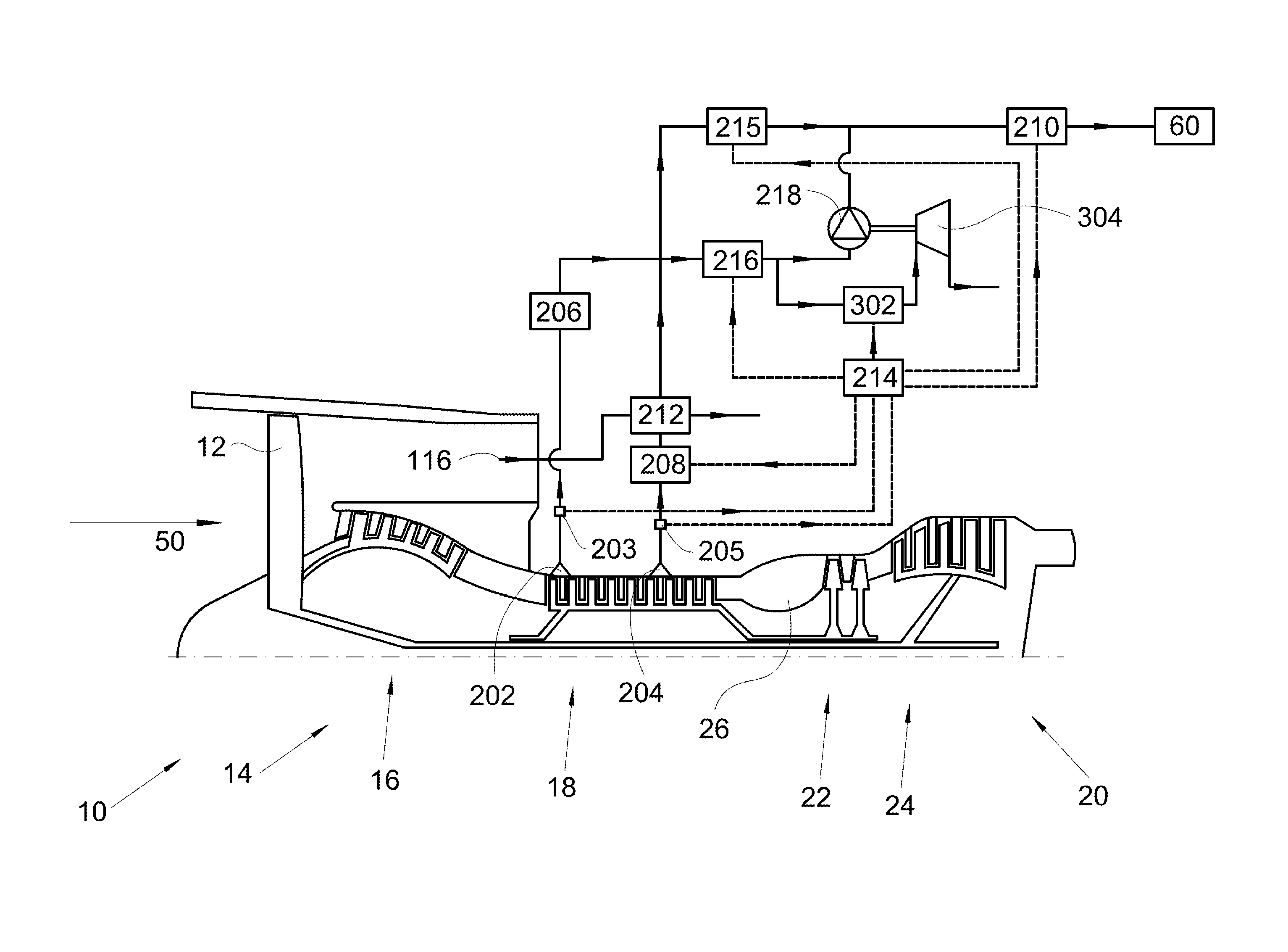
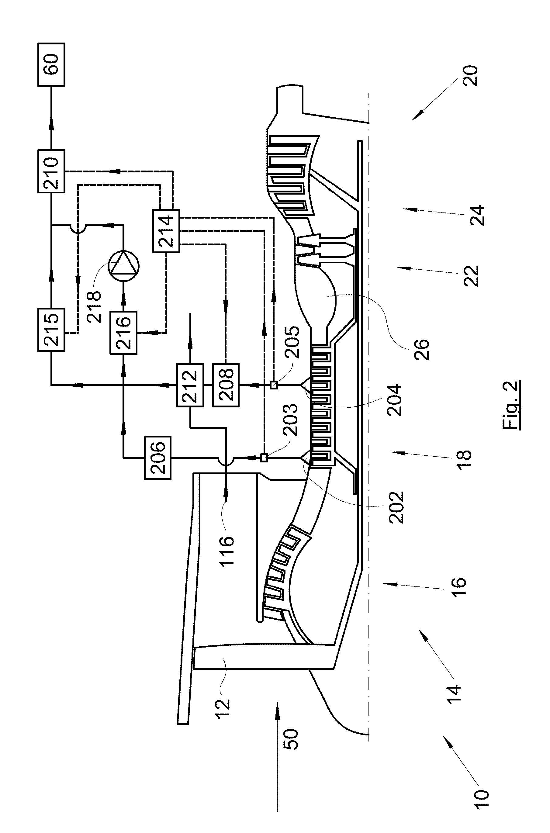
[0052]FIG. 2 and FIG. 3 show the turbojet 10 equipped with a bleeding system 200, 300 according to the invention that is intended to bleed air in the turbojet 10 and to deliver said air to an air system 60, such as the conditioned air system 60 of the aircraft cabin.

[0053]The turbojet 10 comprises the same elements as that in FIG. 1, in particular a low-pressure compressor 16 and a high-pressure compressor 18. These elements bear the same references.

[0054]The high-pressure compressor 18 comprises a number of states of compression in which the pressure rises, from upstream to downstream in a direction of displacement of the air 50 in the turbojet, from a low pressure at the first stage to a high pressure at the last stage, passing through a succession of intermediate pressures at each of the intermediate stages.

[0055]The bleeding system 200 of FIG. 2 comprises:[0056]a first air intake 202 intended to bleed air at low pressure in the high-pressure compressor 18,[0057]a second air inta...


PUM


Abstract

A turbojet comprising a high-pressure compressor with several compression stages in which the pressure rises in a direction of air flow, from a low pressure to a high pressure, passing through intermediate pressures, and a system to bleed air in the turbojet and deliver the air to an air system. The bleeding system comprises a first air intake to bleed air at low pressure, a second air intake to bleed air at an intermediate pressure, a first valve and a second valve having inlets connected to the first air intake, a compressor having an inlet connected to the second valve outlet, a high-pressure valve connected to the second air intake, and a control valve connected to the air system, and a controller to control the opening and closing of the valves depending on the pressures at the first and second air intakes.

Description

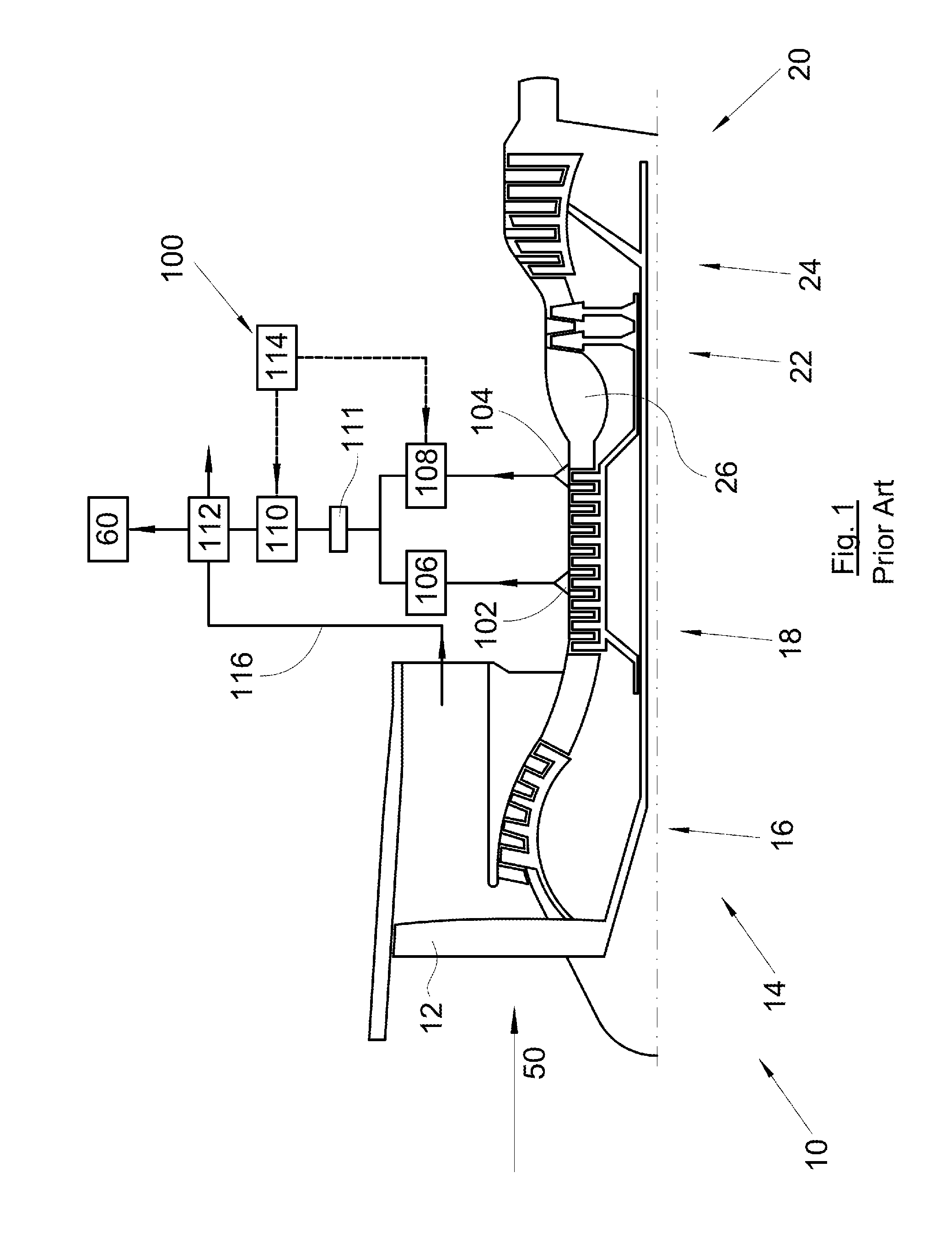
CROSS-REFERENCES TO RELATED APPLICATIONS[0001]This application claims the benefit of the French patent application No. 1451235 filed on Feb. 17, 2014, the entire disclosures of which are incorporated herein by way of reference.BACKGROUND OF THE INVENTION[0002]The present invention relates to an aircraft turbojet comprising a system for bleeding air from said turbojet, an aircraft comprising at least one such turbojet, and a method for controlling such a turbojet.[0003]FIG. 1 shows an aircraft bypass turbojet 10 equipped with a prior art bleeding system 100 that is intended to bleed air in the turbojet 10 and to deliver said air to an air system 60, such as the conditioned air system 60 of the aircraft cabin.[0004]The turbojet 10 comprises:[0005]a fan 12 intended to generate a flow of air in the turbojet 10 in a direction of displacement 50 of air in the turbojet, in which case, as is known, the flow of air then moves downstream of the fan in a primary vein of the turbojet 10 or in a...

Claims


Application Information

Patent Timeline
IPC IPC(8): F02C6/08
CPCB64D13/06F02C6/08F02K3/115B64D13/02B64D13/04B64D2013/0644B64D2013/0648F02C3/10F02C6/04F02C6/06F02C9/18
Inventor PELAGATTI, OLIVIERDEGUIN, THOMASBODET, RONAN
Owner AIRBUS OPERATIONS (SAS)
Learn More