
Method of, and apparatus for, forming hard mask

a mask and hard technology, applied in the field of forming masks, can solve the problems of poor productivity and troublesome control of qualities, and achieve the effects of high film density, reduced film stress, and high film density

Active Publication Date: 2015-08-13
ULVAC INC
View PDF3 Cites 8 Cited by
  • Summary
  • Abstract
  • Description
  • Claims
  • Application Information

AI Technical Summary

Benefits of technology

The technical effect of this patent is to provide a method and apparatus for forming a hard mask with high film quality and resistance to etching. This involves using a single layer of titanium nitride film with low film stress.

Problems solved by technology

However, there were problems, due to the two-layer structure, in that not only must the quality as the entire film be controlled, but also must the qualities of each of the films in the upper-side layer and the lower-side layer be controlled, thereby bringing about the troublesome control of qualities with resultant poor productivity.

Method used


Image

  • Method of, and apparatus for, forming hard mask
  • Method of, and apparatus for, forming hard mask
  • Method of, and apparatus for, forming hard mask

Examples


first embodiment

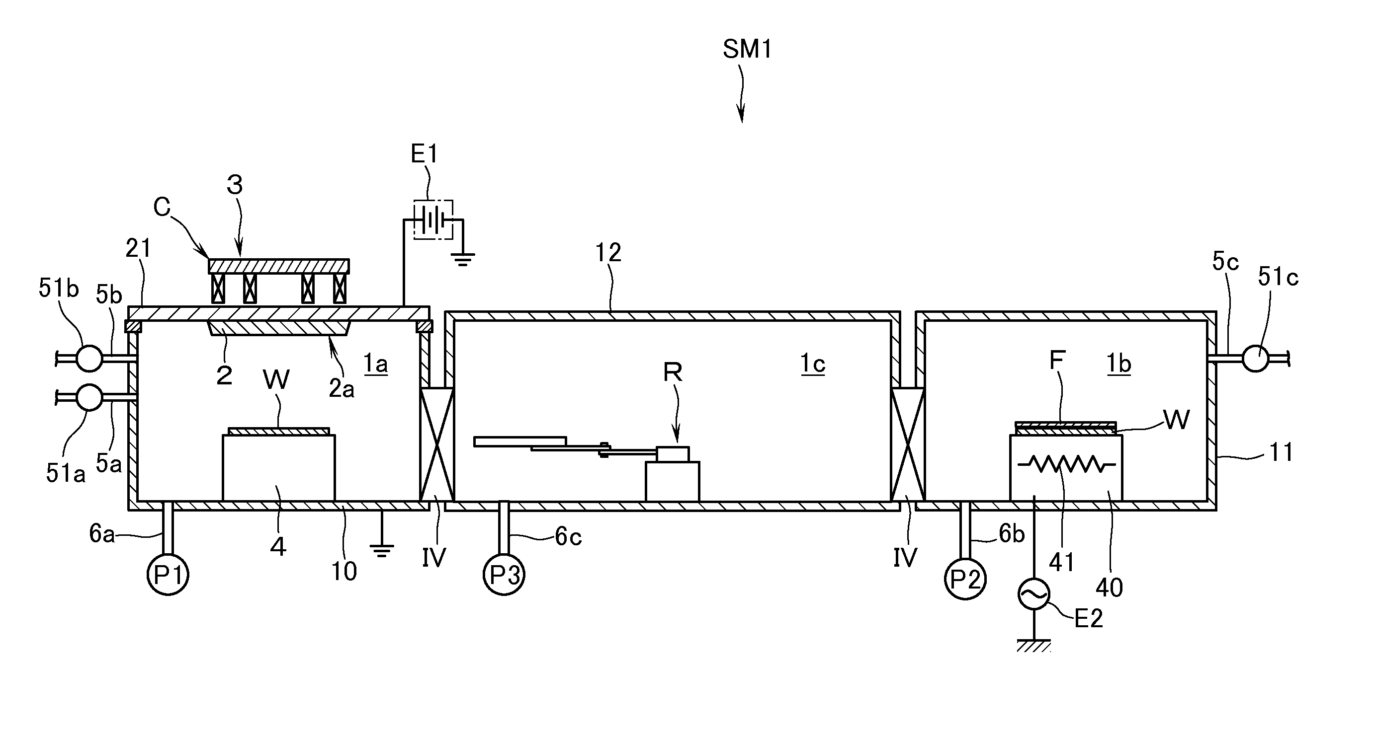
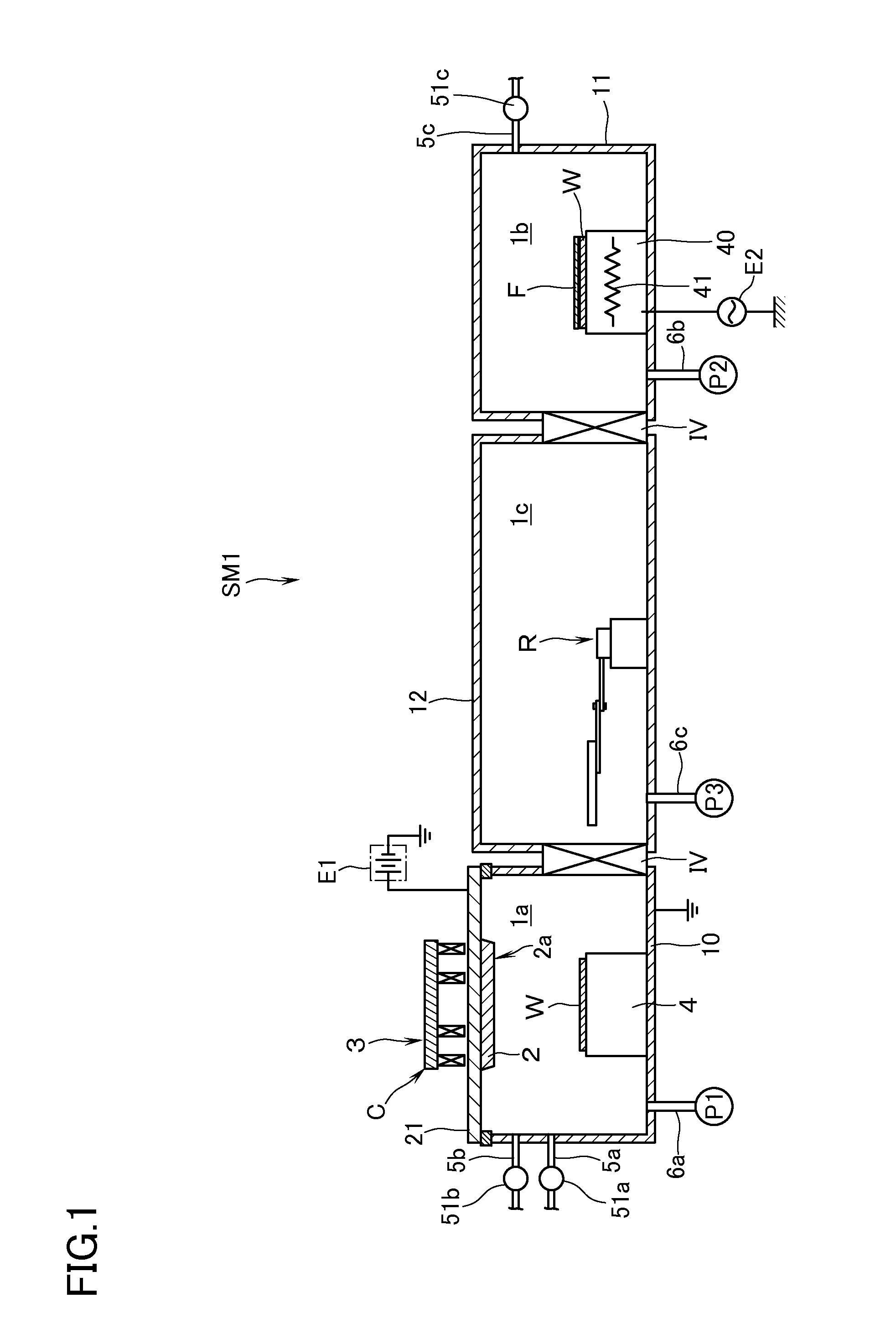
[0016]FIG. 1 shows an example of a sputtering apparatus SM1 as an apparatus for forming a hard mask according to this invention. The sputtering apparatus SM1, which is of a magnetron system, has: a vacuum chamber 10 which defines a first vacuum processing chamber 1a; a vacuum chamber 11 which defines a second vacuum processing chamber 1b; and a transfer chamber 12 which defines a transfer chamber 1c interposed between the first vacuum chamber 10 and the second vacuum chamber 11. The transfer chamber 1c has disposed therein a transfer robot R so that the substrate W can be transferred between the vacuum chambers 10, 11. As the transfer robot R there can be used one having a known structure such, for example, as a frog-leg type. Therefore, detailed explanation thereof will be omitted here. The bottom portion of the transfer chamber 12 has connected thereto an exhaust pipe 6c which is in communication with a vacuum exhaust means P3 which is made up of a rotary pump and the like. The va...

second embodiment

[0026]FIG. 2 shows an example of a sputtering apparatus SM2 as an apparatus for forming a hard mask according to this invention. The sputtering apparatus SM2 is of a magnetron system and has a vacuum chamber 10 which defines a vacuum processing chamber 1a. An explanation will now be made of a case in which the depositing step, the adsorbing step, and the heating step are carried out in one and the same vacuum processing chamber 1a. The side wall of the vacuum chamber 10 has connected thereto a first gas pipe 5a for introducing rare gas, a second gas pipe 5b for introducing nitrogen gas and, in addition, a third gas pipe 5c for introducing oxygen-containing gas such as oxygen gas, H2 O gas and the like to be used in the adsorbing step. The third gas pipe 5c has interposed therein a mass flow controller 51c. The gas pipe 5c and the mass flow controller 51c constitute “oxygen-containing gas introducing means” of this invention. The stage 4 has connected thereto an output from the bias ...


PUM

PropertyMeasurementUnit
temperatureaaaaaaaaaa

Abstract

A method of forming a hard mask includes depositing step for depositing a titanium nitride film on a surface of a to-be-processed object; adsorbing step for adsorbing oxygen-containing molecules onto a surface of the titanium nitride film; and heating step for heating the titanium nitride film to a predetermined temperature.

Description

[0001]The present invention relates to a method of, and apparatus for, forming a hard mask which is constituted by a titanium nitride film.BACKGROUND ART[0002]In manufacturing processes, e.g., of semiconductor equipment, when an interlayer dielectric (or insulation) film as an object to be processed (hereinafter also referred to as a “to-be-processed object”) is dry-etched in order to obtain a predetermined wiring pattern, a titanium nitride film is used as a hard mask which restricts the etching range. As this kind of hard mask, there is known one which is made up of a single layer of titanium nitride film (see, e.g., JP-A-2008-91915). The titanium nitride film for use as a hard mask requires etching resistance (etching durability) and, therefore, the film density shall preferably be high. On the other hand, if the film stress is high, at the time when the interlayer dielectric (insulation) film is subjected to dry etching, the etching shape changes as a whole or locally and, conse...

Claims


Application Information

Patent Timeline
Patent Type & Authority Applications(United States)
IPC IPC(8): H01L21/308C23C16/46C23C16/06C23C16/455
CPCH01L21/3086H01L21/3081C23C16/06C23C16/46C23C16/455C23C14/0641C23C14/5806C23C14/5826C23C14/584H01L21/31144H01L21/32051H01L21/321H01L21/0273
Inventor NAKANO, KATSUAKI
Owner ULVAC INC
Learn More