
Carbonyl derivative, liquid crystal composition containing compound thereof and liquid crystal display device

a liquid crystal display device and carbonyl derivative technology, applied in liquid crystal compositions, chemistry apparatus and processes, organic chemistry, etc., can solve the problems of shortening the service life of the device and reducing the electric power consumption of the device, and achieves high clearing point, small viscosity, and high heat resistance.

Active Publication Date: 2015-08-06
JNC CORP +1
View PDF2 Cites 3 Cited by
  • Summary
  • Abstract
  • Description
  • Claims
  • Application Information

AI Technical Summary

Benefits of technology

The invention provides a liquid crystal compound with excellent stability, clarity, low minimum temperature, small viscosity, and suitable optical and electrical properties. The compound can be mixed with other liquid crystal compounds to create a liquid crystal composition with a wide temperature range, short response time, high voltage holding ratio, low threshold voltage, and long service life. The resulting liquid crystal display device has high contrast and performance.

Problems solved by technology

Among the modes, the IPS mode, the FFS mode and the VA mode are known to improve narrowness of a viewing angle being a disadvantage of the operating mode such as the TN mode and the STN mode.
Thus, a service life of the device becomes long.
Thus, an electric power consumption of the device is decreased.
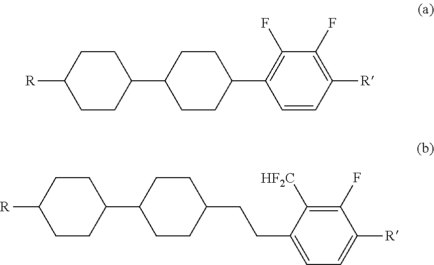
However, while compounds (a), (b) and (c) have negative dielectric anisotropy (Δε), values thereof is not always large in several cases, and may be insufficient in the order to reduce a driving voltage of the liquid crystal display device having the modes such as the VA mode and the IPS mode in several cases.

Method used


Image

  • Carbonyl derivative, liquid crystal composition containing compound thereof and liquid crystal display device
  • Carbonyl derivative, liquid crystal composition containing compound thereof and liquid crystal display device
  • Carbonyl derivative, liquid crystal composition containing compound thereof and liquid crystal display device

Examples


example 1

Synthesis of Compound (1-1-2)

[0226]

First Step

[0227]In a reaction vessel, 4-bromo-2-fluorophenol (t-1) (48 g, 252 mmol), potassium carbonate (69.6 g, 504 mmol), tetrabutylammonium bromide (TBAB; 4.07 g, 12.6 mmol) and N,N-dimethylformamide (DMF; 400 mL) were put. Ethyl iodide (78.6 g, 504 mmol) was slowly added dropwise thereto at room temperature, and then the resulting mixture was stirred at room temperature for 5 hours. The resulting reaction mixture was poured into saturated brine, and subjected to extraction with hexane. Organic layers combined were washed with water and saturated brine, and dried over anhydrous sodium sulfate. The resulting solution was concentrated under reduced pressure, and the residue was purified by distillation under reduced pressure to give compound (t-2) (49.6 g, 226 mmol; 89.7%).

Second Step

[0228]Under a nitrogen atmosphere, compound (t-2) (40 g, 182.6 mmol) obtained in the first step and THF (600 mL) were put in a reaction vessel, and then cooled to −7...

example 2

Synthesis of Compound (1-2-1)

[0235]

First Step

[0236]Compound (t-7) (g, mmol; %) was obtained by performing operations in a manner similar to the operations in the fourth step in Example 1, using compound (t-4) (g, mmol) obtained in the third step in Example 1, THF (55 mL), a THF solution (1.3 M, mL, mmol) of isopropylmagnesium bromide and lithium chloride, and aldehyde (t-6) (g, mmol).

Second Step

[0237]Object compound (1-2-1) (g, mmol; %) was obtained by performing operations in a manner similar to the operations in the fifth step in Example 1, using compound (t-7) (g, mmol) obtained in the first step, dichloromethane (60 mL) and Dess-Martin periodinane (DMP; g, mmol).

[0238]1H-NMR (CDCl3) δ 7.42 (d, 1H), 7.25 (t, 1H; CF2H, J=53.3), 7.04 (t, 1H), 4.17 (q, 2H), 2.75 (d, 2H), 1.91-1.72 (m, 5H), 1.51 (t, 3H), 1.37-1.12 (m, 4H), 1.02-0.91 (m, 4H), 0.86 (t, 3H).

[0239]Physical properties of compound (1-2-1) were as described below.

[0240]Phase transition temperature: C 61.0 I.

Maximum temperat...

example 3

Synthesis of Compound (1-4-1)

[0241]

First Step

[0242]Compound (t-11) (2.12 g, 4.52 mmol; 33.1%) was obtained by performing operations in a manner similar to the operations in the fourth step in Example 1, using compound (t-4) (4.78 g, 17.74 mmol) obtained in the third step of Example 1, THF (80 mL), a THF solution (1.3 M, 13.64 mL, 17.74 mmol) of isopropylmagnesium bromide and lithium chloride, and aldehyde (t-10) (3.8 g, 13.64 mmol).

Second Step

[0243]Object compound (1-4-1) (0.74 g, 1.59 mmol; 70.1%) was obtained by performing operations in a manner similar to the operations in the fifth step in Example 1, using compound (t-11) (1.06 g, 2.26 mmol) obtained in the first step, dichloromethane (15 mL) and Dess-Martin periodinane (DMP; 1.44 g, 3.39 mmol).

[0244]1H-NMR (CDCl3) δ 7.43 (d, 1H), 7.39 (t, 1H; CF2H, J=53.3), 7.04 (t, 1H), 4.16 (q, 2H), 2.86 (t, 2H), 1.76-1.66 (m, 6H), 1.51 (t, 3H), 1.28-1.11 (m, 8H), 1.01-0.82 (m, 13H).

[0245]Physical properties of compound (1-4-1) were as descri...


PUM

PropertyMeasurementUnit
Compositionaaaaaaaaaa

Abstract

To provide a liquid crystal compound satisfying at least one of physical properties such as a high stability to heat, light and so forth, a high clearing point, a low minimum temperature of a liquid crystal phase, a small viscosity, a suitable optical anisotropy, a large dielectric anisotropy, a suitable elastic constant and an excellent compatibility with other liquid crystal compounds; a liquid crystal composition containing the compound; and a liquid crystal display device including the composition. The compound is represented by formula (1):wherein, for example, Ra and Rb are alkyl having 1 to 10 carbons, alkenyl having 2 to 10 carbons or alkoxy having 1 to 9 carbons; A1, A2 and A3 are 1,4-cyclohexylene or 1,4-phenylene; Z1 and Z2 are single bonds, —(CH2)2—, —CH═CH—, —COO—, —OCO—, —CF2O—, —OCF2—, —CH2O— or —OCH2—; Y1 is —CF2H or —CF3; Y2 is fluorine; and a, b and d are 0, 1, 2 or 3, and c is 1 or 3.

Description

TECHNICAL FIELD[0001]The invention relates to a liquid crystal compound being a carbonyl derivative, a liquid crystal composition and a liquid crystal display device. More specifically, the invention relates to a compound that has an alkyloxy or alkyleneoxy skeleton and has a negative dielectric anisotropy, a liquid crystal composition containing the compound, and a liquid crystal display device including the composition.BACKGROUND ART[0002]A liquid crystal display device is widely utilized for a display of a personal computer, a television and so forth. The device utilizes optical anisotropy, dielectric anisotropy and so forth of a liquid crystal compound. As an operating mode of the liquid crystal display device, various modes are known, such as a phase change (PC) mode, a twisted nematic (TN) mode, a super twisted nematic (STN) mode, a bistable twisted nematic (BTN) mode, an electrically controlled birefringence (ECB) mode, an optically compensated bend (OCB) mode, an in-plane sw...

Claims


Application Information

Patent Timeline
IPC IPC(8): C09K19/34C07C49/84C07C62/38C07D309/06C07D493/08C07D319/06C09K19/30C07C49/80
CPCC09K19/3402C09K19/3003C09K19/3068C09K19/3028C09K19/3066C07C49/84C07C49/80C07D309/06C07D493/08C07D319/06C07C62/38C09K2019/3009C09K2019/301C09K2019/3078C09K2019/3075C09K2019/3036C09K2019/3422C09K2019/0425C09K19/062C09K19/14C09K19/32C09K19/322C09K2019/0444C09K2019/3425C07C2601/14
Inventor GOTO, MAYUMI
Owner JNC CORP
Learn More