
Surface inspection apparatus for semiconductor chips

a surface inspection and semiconductor chip technology, applied in the direction of optical radiation measurement, instruments, television systems, etc., can solve the problems of large amount of inspection time, non-destructive inspection, and remarkably reduced inspection accuracy, so as to improve the overall manufacturing efficiency of semiconductor chips, reduce time and accuracy, and improve the time and accuracy of surface inspection process

Active Publication Date: 2015-07-23
SAMSUNG ELECTRONICS CO LTD +1
View PDF10 Cites 16 Cited by
  • Summary
  • Abstract
  • Description
  • Claims
  • Application Information

AI Technical Summary

Benefits of technology

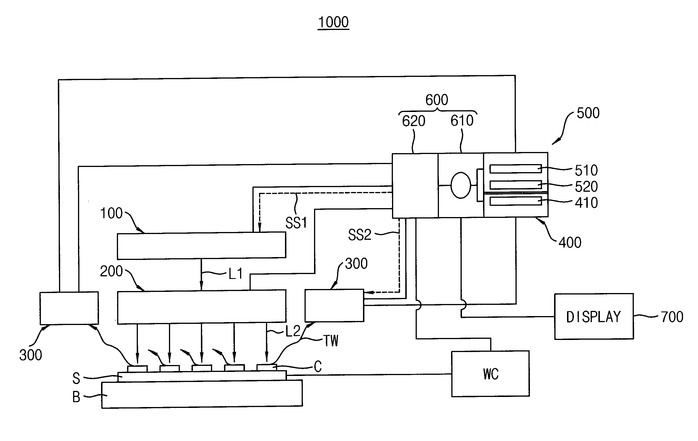
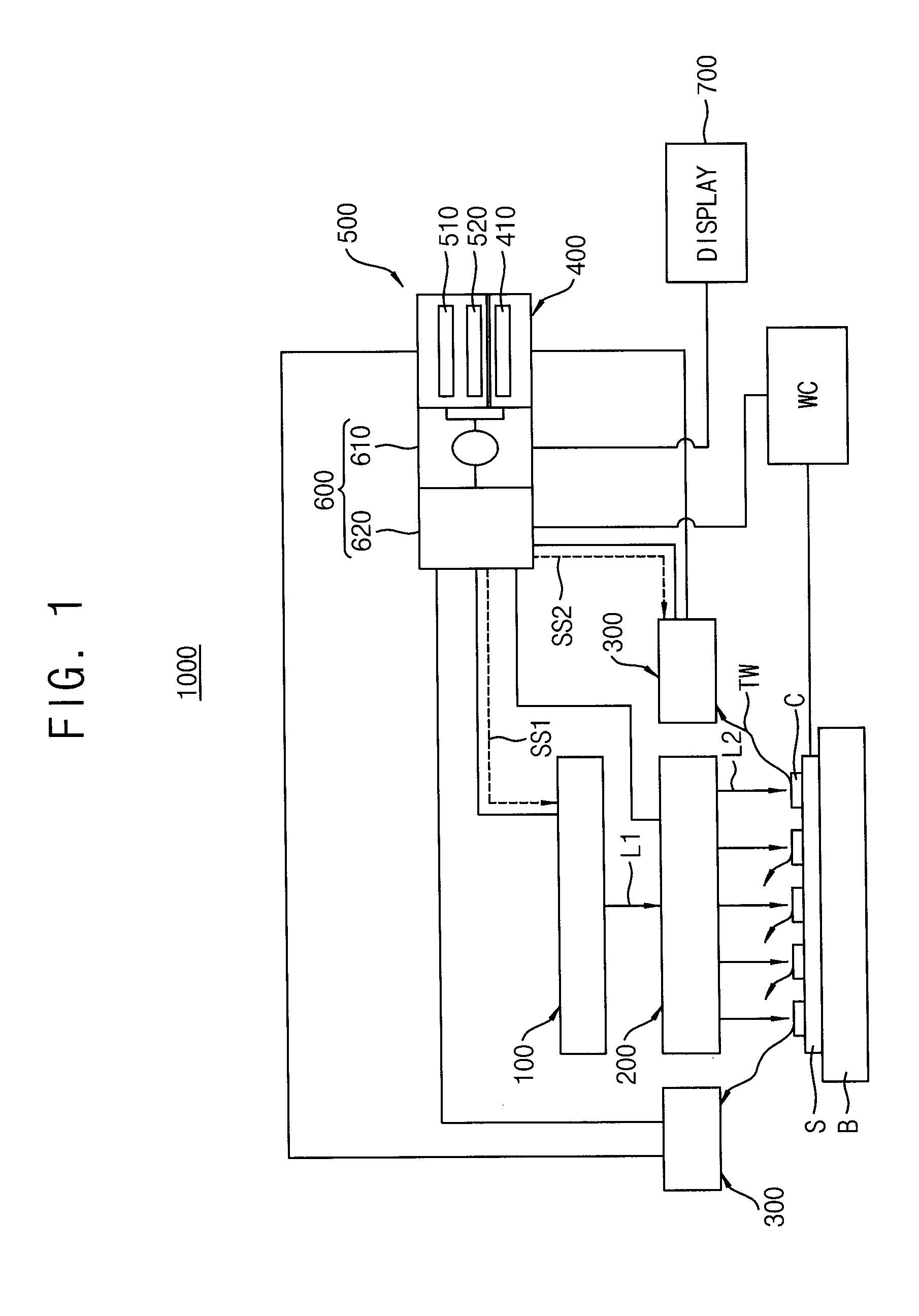
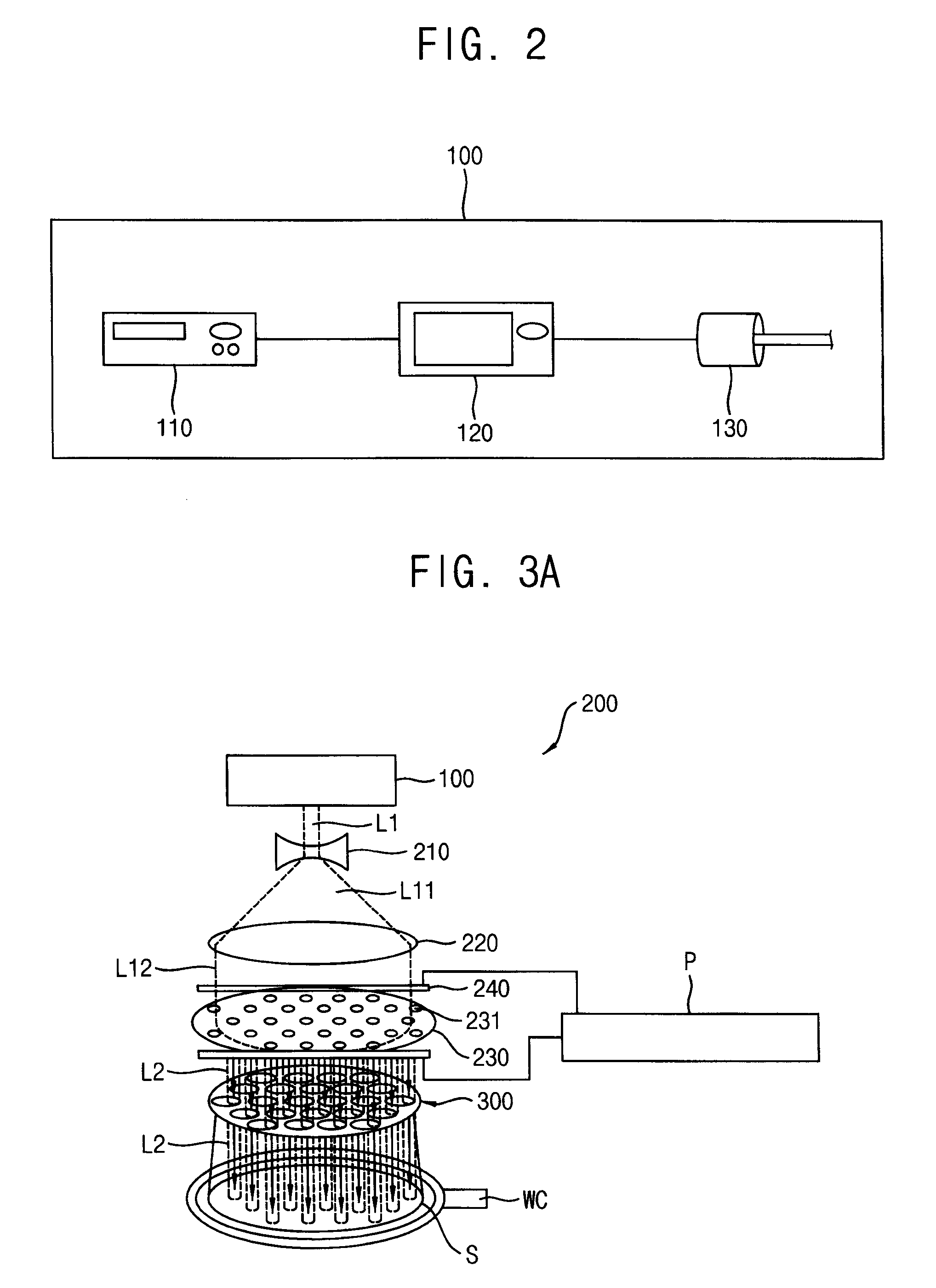
The present invention provides an improved surface inspection apparatus and method that can reduce inspection time and improve accuracy and efficiency. A periodic continuous wave (CW) laser is irradiated to a semiconductor chip surface, and the lock-in amplitude images of the chip surface are generated, thereby increasing inspection accuracy and reducing inspection time. The CW layer is transformed into an inspection laser beam, which can simultaneously and partially excite multiple semiconductor chips. The thermal images generated from the chip surface scanning points are processed using lock-in amplitude technology and hold exponent technology, allowing for accurate and clear surface image display of surface defects. This surface inspection process improves overall manufacturing efficiency of semiconductor chips.

Problems solved by technology

However, the conventional non-destructive inspection apparatus usually requires a minimal defect size and the absence of foreign matter on a surface of the semiconductor chips for sufficient accuracy of the surface inspection.
Particularly, when foreign matter is not sufficiently removed from the chip surface, the inspection accuracy is remarkably decreased.
This necessarily requires a large amount of inspection time, which significantly reduces the overall manufacturing efficiency of the semiconductor chips.
Furthermore, an optical inspection technique, one of the most widely used non-destructive inspection techniques, is sensitive to the surface conditions of the chip and the presence of a minor amount of foreign matter on the surface tends to cause an inspection error and finally to interrupt the operation of the inspection apparatus, which results in a great increase of the inspection time for the semiconductor chips.

Method used


Image

  • Surface inspection apparatus for semiconductor chips
  • Surface inspection apparatus for semiconductor chips
  • Surface inspection apparatus for semiconductor chips

Examples


Embodiment Construction

[0056]Various example embodiments will be described more fully hereinafter with reference to the accompanying drawings, in which some example embodiments are shown. The present inventive concepts may, however, be embodied in many different forms and should not be construed as limited to the example embodiments set forth herein. Rather, these example embodiments are provided so that this disclosure will be thorough and complete, and will fully convey the scope of the present inventive concepts to those skilled in the art. In the drawings, the sizes and relative sizes of layers and regions may be exaggerated for clarity.

[0057]It will be understood that when an element or layer is referred to as being “on,”“connected to” or “coupled to” another element or layer, it can be directly on, connected or coupled to the other element or layer or intervening elements or layers may be present. In contrast, when an element is referred to as being “directly on,”“directly connected to” or “directly...


PUM


Abstract

A surface inspection apparatus and method of inspecting chip surfaces includes a laser generator that generates a periodic CW laser and is transformed into an inspection laser beam having a beam size smaller than a surface size of the chip. Thus, the inspection laser beam is irradiated onto a plurality of the semiconductor chips such that the semiconductor chips are partially and simultaneously heated. Thermal waves are detected in response to the inspection laser beam and thermal images are generated corresponding to the thermal waves. A surface image is generated by a lock-in thermography technique and hold exponent analysis of the thermal image, thereby generating surface image in which a surface defect is included. Time and accuracy of the surface inspection process is improved.

Description

CROSS-REFERENCE TO RELATED APPLICATIONS[0001]This application claims benefit under 35 U.S.C §119 to Korean Patent Application No. 10-2014-0008579 filed on Jan. 23, 2014 in the Korean Intellectual Property Office, the disclosure of which is incorporated by reference herein in its entirety.BACKGROUND[0002]1. Field[0003]Example embodiments relate to a surface inspection apparatus and method of inspecting surfaces of semiconductor chips using the same, and more particularly, to a non-destructive surface inspection apparatus for semiconductor chips and a method of inspecting surfaces of semiconductor chips non-destructively using the same.[0004]2. Description of the Related Art[0005]Various non-destructive inspection technologies have been suggested and used for surface inspection of semiconductor chips. However, the conventional non-destructive inspection apparatus usually requires a minimal defect size and the absence of foreign matter on a surface of the semiconductor chips for suffic...

Claims


Application Information

Patent Timeline
IPC IPC(8): G01N21/95G06T7/00H04N5/33G01J5/10G01J5/08
CPCG01N21/9501G01J5/10G01J5/0896H04N5/33G06T7/0008G01J2005/0081G01J5/0803G01J5/047G01J5/0007G01J5/025G01J5/026G01J2005/0077G01J5/0806G01J5/0831G01N2201/06113G01J5/802G01J5/48G01J5/80H04N23/23
Inventor MUN, YOUN-JOSOHN, HOONKIM, SANG-YOUNGAN, YUN-KYUCHO, SUNG-ILHA, SEUNG-WEONYANG, JIN-YEOLHWANG, SOON-KYU
Owner SAMSUNG ELECTRONICS CO LTD
Learn More