
System for improving the purifying liquid evaporation in an axially symmetric dosing module for an scr device

a technology of axially symmetric dosing module and scr device, which is applied in the direction of flow mixer, exhaust treatment, mixer, etc., can solve the problems of less efficient heat transfer at low mean gas velocity, reduced heat exchange ability, and evaporation process, so as to reduce the associated cooling effect, reduce the spray mass flux, and increase the area of spray distribution

Active Publication Date: 2015-06-18
FPT MOTORENFORSCHUNG
View PDF8 Cites 9 Cited by
  • Summary
  • Abstract
  • Description
  • Claims
  • Application Information

AI Technical Summary

Benefits of technology

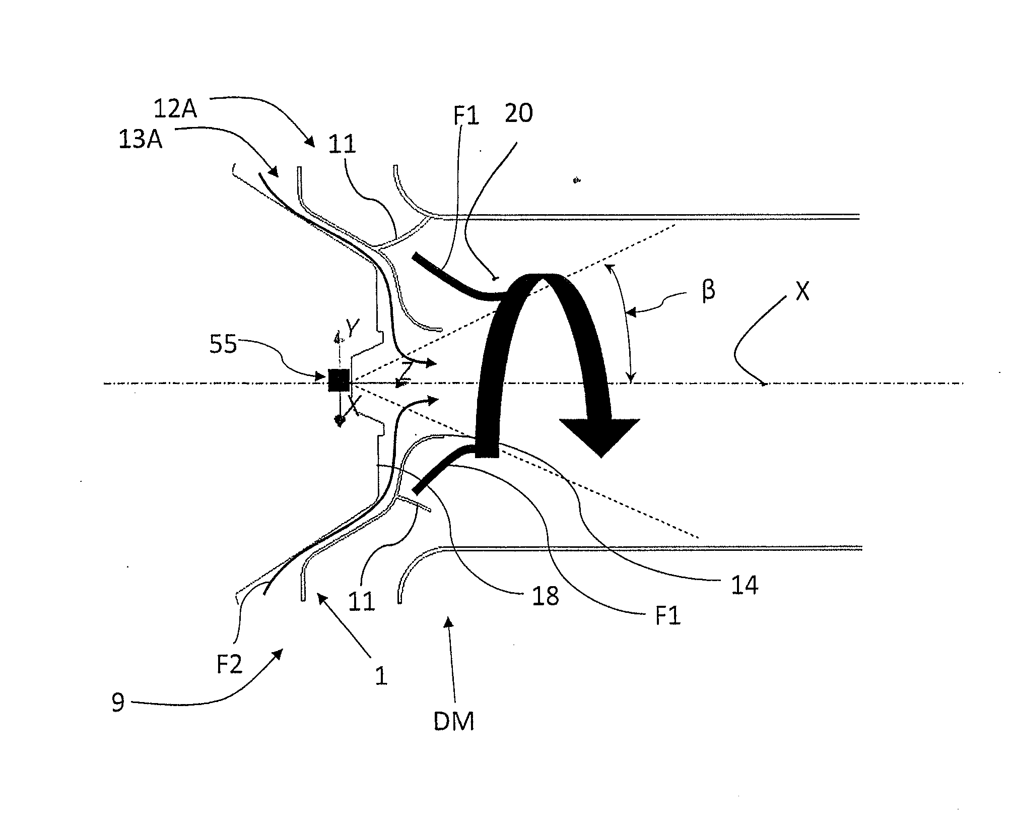
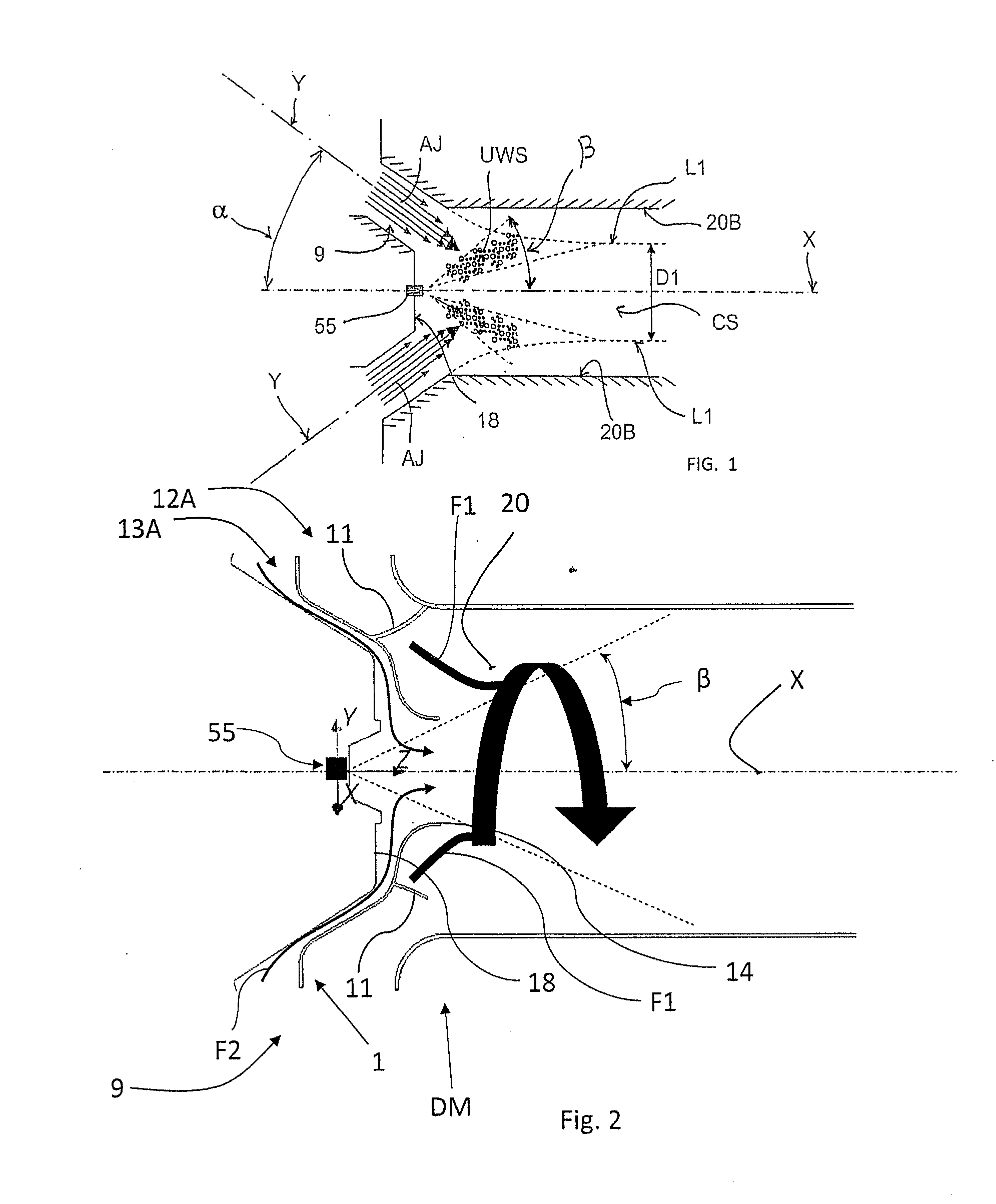
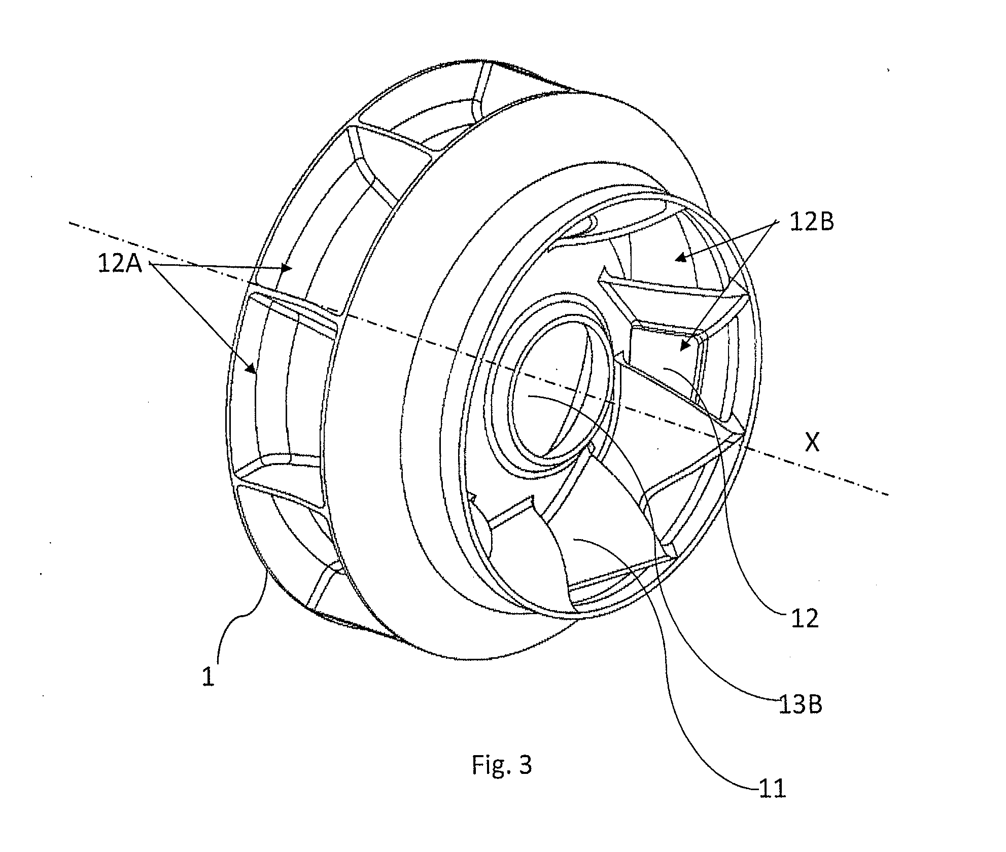
This invention describes a device that splits the gas stream into two different directions where a urea based agent is sprayed. The innermost gas stream is directed towards the housing where the spray is sprayed, while the outer gas stream is directed towards the nozzle. The inner gas stream is accelerated to improve the mixing effect. This design reduces deposits near the injection point and increases the area of spray distribution. It also reduces cooling effects on the pipe walls and enhances the evaporation of liquid droplets. The inner gas stream is introduced close to the nozzle, while the outer gas stream is introduced far from the nozzle to improve the mixing effect.

Problems solved by technology

However, at lower exhaust gas temperature there is not only less available energy, although still sufficient, but the available temperature difference, between the exhaust gasses and the injected liquid, which enable the heat exchange is much reduced.
Another factor worsens the evaporation process, namely the fact that the heat transfer is less efficient at low mean gas velocities.
This is an unacceptable behavior due to wrong NH3 dosing to the SCR system and / or increased back pressure.

Method used


Image

  • System for improving the purifying liquid evaporation in an axially symmetric dosing module for an scr device
  • System for improving the purifying liquid evaporation in an axially symmetric dosing module for an scr device
  • System for improving the purifying liquid evaporation in an axially symmetric dosing module for an scr device

Examples


Embodiment Construction

[0030]The present invention refers to an improved dosing module DM according to the invention comprises a housing 20 which develops symmetrically along an axis X (also indicated with longitudinal axis X). In this regard, such dosing module is suitable to be integrated or added upstream of an SCR of an aftertreatment system of a combustion engine.

[0031]The dosing module comprises a housing 20 in which the urea-based reducing agent is injected as a spray.

[0032]The dosing module can be a part of the exhaust pipe upstream of the catalyst or part of the catalyst itself. The housing can have preferably a circular cross section. For the purpose of the invention, by the expression “cross section” or “transversal section” it is meant a section perpendicular to the development axis X.

[0033]The dosing module DM comprises an annular inlet opening 9, see FIG. 1, for conveying the exhaust gas stream, coming from the engine, into said housing 20.

[0034]The dosing module DM also comprises dosage mea...


PUM

PropertyMeasurementUnit
half-cone opening angleaaaaaaaaaa
angleaaaaaaaaaa

Abstract

Device for improving the purifying liquid evaporation in an axially symmetric dosing module for an SCR device. The dosing module is able to dose a urea-based reducing agent into a gas exhaust stream generated by a combustion engine. The dosing module comprises a housing developing symmetrically along a development axis; a nozzle for dosing the urea-based reducing agent, arranged along said development axis; and an inlet opening for conveying the gas exhaust stream into the dosing housing, arranged annularly with respect to the nozzle. The device further includes a splitting wall, arranged within the inlet opening for defining at least two separate annular gas stream paths, one annular and coaxial with respect to another, one of them shaped for inducing a different axial speed into a respective gas stream with respect to another.

Description

BACKGROUND OF THE INVENTION[0001]1. Field of the Invention[0002]The present invention relates to a device for improving the purifying liquid evaporation in an axially symmetric dosing module for an SCR device.[0003]2. Description of the Related Art[0004]Aftertreatment systems are, commonly, used to reduce emissions. The NOx reduction is mainly realized by a selective catalytic reduction (SCR) system. The required Ammonia (NH3) for the reduction of the NOx is usual injected as a liquid with dissolved UREA, commonly AdBlue or DEF (water with 32.5% UREA).[0005]An example of axially symmetric evaporation device is given in EP2339137.[0006]The evaporation of the liquid (water) and the decomposition (thermolysis and hydrolysis) of the UREA requires some energy. This energy is usually delivered by the exchange with hot exhaust gas. However, at lower exhaust gas temperature there is not only less available energy, although still sufficient, but the available temperature difference, between ...

Claims


Application Information

Patent Timeline
Patent Type & Authority Applications(United States)
IPC IPC(8): F01N3/20F01N3/28
CPCF01N3/28F01N3/208F01N3/2066F01N3/2892F01N3/36F01N2240/20F01N2610/02F01N2610/1453Y02A50/20Y02T10/12B01F23/2132B01F2025/931B01F25/313
Inventor ASSALVE, DANIELCAMPBELL, JOHNFESSLER, HARALDSCHLEGEL, RETO
Owner FPT MOTORENFORSCHUNG
Learn More