Eureka AIR delivers breakthrough ideas for toughest innovation challenges, trusted by R&D personnel around the world.

Solid, ionically conducting polymer material, and methods and applications for same

a polymer material and ion-conducting technology, applied in the direction of non-metal conductors, cell components, sustainable manufacturing/processing, etc., can solve the problems of slow charge time, limited rechargeable number, and eventual failure of batteries of conventional lithium ion batteries, etc., to achieve low effective aqueous porosity, low or high surface area

Active Publication Date: 2015-06-04
IONIC MATERIALS INC
View PDF7 Cites 81 Cited by
  • Summary
  • Abstract
  • Description
  • Claims
  • Application Information

AI Technical Summary

Benefits of technology

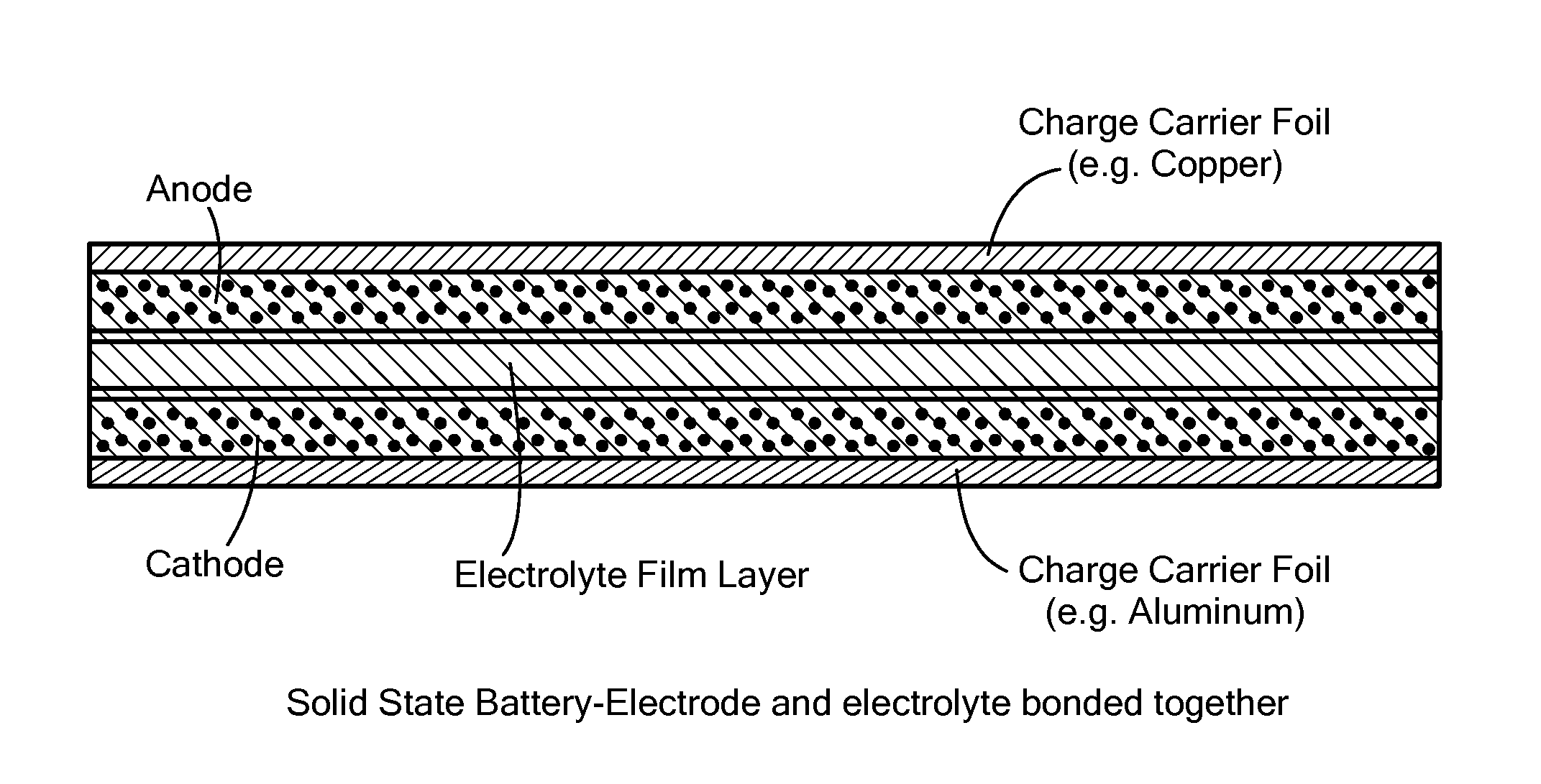
The patent is about a new material that can be used as a separator in batteries. It is made up of a solid, ionically conductive polymer that can allow for the movement of ions between different parts of the battery. It can be shaped like a film or coated onto electrodes to isolate them from other parts of the battery. The material can also have high or low surface area and porosity, depending on the needs of the battery. The patent allows for the creation of new, custom-shaped materials that can improve the performance of batteries.

Problems solved by technology

Conventional batteries have limitations, however.
For example, lithium ion and other batteries generally employ a liquid electrolyte which is hazardous to humans and to the environment and which can be subject to fire or explosion.
Conventional liquid electrolyte suffers from the build-up of a solid interface layer at the electrode / electrolyte interface which causes eventual failure of the battery.
Conventional lithium ion batteries also exhibit slow charge times and suffer from a limited number of recharges since the chemical reaction within the battery reaches completion and limits the rechargeability because of corrosion and dendrite formation.
Formation of the same ions which saturated the electrolyte may hinder discharging, however.
The formation of soluble low valent species (e.g., Mn species during discharge of Zn / MnO2 batteries) can adversely affect the utilization of active material however.
Crystalline structure rearrangement with formation of inactive phases and out-diffusion of soluble products limits cathode capacity.
However, there is no data to suggest that a complete cell utilizing these cathodes was built or that this worked using a Zn anode.
While these methods have met with various degrees of success in limiting the polysulfide shuttle mechanism, they all rely on the use of expensive materials which are not well suited to large scale manufacturing.

Method used


Image

  • Solid, ionically conducting polymer material, and methods and applications for same
  • Solid, ionically conducting polymer material, and methods and applications for same
  • Solid, ionically conducting polymer material, and methods and applications for same

Examples


example 1

[0156]Solid polymer electrolyte was made by mixing PPS base polymer and ion source compound LiOH monohydrate in the proportion of 67% to 33% (by wt.), respectively, and mixed using jet milling. DDQ dopant was added to the resulting mixture in the amount of 1 mole of DDQ per 4.2 moles of PPS. The mixture was heat treated at 325 / 250° C. for 30 minutes under moderate pressure (500-1000 PSI). After cooling, the resulting material was grinded and placed into NMR fixture.

[0157]Self-diffusion coefficients were determined by using pulsed field gradient solid state NMR technique. The results shown in FIGS. 19 and 20 indicate, respectively, that Li+ and OH− diffusivity in the solid polymer electrolyte is the highest of any known solid, and over an order of magnitude higher at room temperature compared to recently developed L10GeP2S12 ceramic at much higher temperatures (140° C.) or the best PEO formulation at 90° C.

example 2

[0158]PPS base polymer and ion source compound LiOH monohydrate were added together in the proportion of 67 wt. % to 33 wt. %, respectively, and mixed using jet milling. Cathode was prepared by additionally mixing 50% β-MnO2 from Alfa Aesar, 5% of Bi2O3 and 15% of C45 carbon black. DDQ dopant was added to the resulting mixture in the amount of 1 mole of DDQ per 4.2 moles of PPS.

[0159]The mixture was compression molded onto stainless steel mesh (Dexmet) at 325 / 250° C. for 30 minutes under moderate pressure (500-1000 PSI), yielding cathode disc 1 inch in diameter and about 0.15 mm thick. The resulting disc was punched to 19 mm diameter and used as a cathode to assemble test cells, containing commercial non-woven separator (NKK) and Zn foils anode. 6M LiOH was added as electrolyte.

[0160]Cells were discharged under constant current conditions of 0.5 mA / cm2 using Biologic VSP test system. The specific capacity of MnO2 was 303 mAh / g or close to theoretical 1e− discharge. FIG. 21 illustrat...

example 3

[0161]PPS base polymer and ion source compound LiOH monohydrate were added together in the proportion of 67% to 33% (by wt.), respectively, and mixed using jet milling. Cathode was prepared by additionally mixing 50% β-MnO2 form Alfa Aesar, 5% of Bi2O3 and 15% of C45 carbon black. DDQ dopant was added to the resulting mixture in the amount of 1 mole of DDQ per 4.2 moles of PPS.

[0162]The mixture was compression molded onto stainless steel mesh (Dexmet) at 325 / 250 C for 30 minutes under moderate pressure (500-1000 psi), yielding cathode disc 1″ in diameter and 1.6-1.8 mm thick.

[0163]The resulting cathodes were used to assemble test cells, containing commercial non-woven separator (NKK) and Zn anode slurry extracted from commercial alkaline cells. 6M KOH solution in water was used as electrolyte.

[0164]Cells were discharged under constant current conditions using Biologic VSP test system. The specific capacity of MnO2 was close to 600 mAh / g at C / 9 discharge rate (35 mA / g), or close to t...


PUM

PropertyMeasurementUnit
Fractionaaaaaaaaaa
Fractionaaaaaaaaaa
Fractionaaaaaaaaaa

Abstract

The invention features a rechargeable alkaline battery comprising an anode; a cathode; and an electrolyte; wherein at least one of anode, the cathode and the electrolyte includes a solid, ionically conducting polymer material, and methods for the manufacture of same.

Description

STATEMENT REGARDING FEDERALLY SPONSORED RESEARCH OR DEVELOPMENT[0001](Not applicable)BACKGROUND OF THE INVENTION[0002]Batteries have become increasingly important in modern society, both in powering a multitude of portable electronic devices, as well as being key components in new green technologies. These new technologies offer the promise of removing the dependence on current energy sources such as coal, petroleum products, and natural gas which contribute to the production of by-product green-house gases. Furthermore, the ability to store energy in both stationary and mobile applications is critical to the success of new energy sources, and is likely to sharply increase the demand for all sizes of advanced batteries. Especially for batteries for large applications, a low base cost of the battery will be key to the introduction and overall success of these applications.[0003]Conventional batteries have limitations, however. For example, lithium ion and other batteries generally em...

Claims


Application Information

Patent Timeline
IPC IPC(8): H01M4/60H01M4/50H01M4/04H01M10/24H01M4/62H01M4/36H01M4/06H01M50/411
CPCH01M4/602H01M4/364H01M4/50H01M4/049H01M10/24H01M4/625H01M4/626H01M4/06H01M4/624H01M4/0411H01M4/24H01M4/38H01M4/42H01M4/48H01M4/58H01M10/26H01M6/181H01M2300/0082H01M4/502H01M4/62H01M4/622H01M10/054H01M10/0565Y02P70/50Y02E60/10H01M4/244H01M4/46H01M4/13
Inventor ZIMMERMAN, MICHAEL A.GAVRILOV, ALEXEI G.
Owner IONIC MATERIALS INC
Why Eureka
Eureka Blog
Learn More