Heat transfer tube and cracking furnace using the same

a technology of heat transfer tube and cracking furnace, which is applied in the direction of indirect heat exchanger, mechanical equipment, lighting and heating apparatus, etc., can solve the problems of reducing the resistance of fluid, further reducing the pressure loss of fluid, and poor effect of heat transfer tube, so as to improve the tangential speed of fluid, enhance heat transfer, and reduce the resistance of fluid

Active Publication Date: 2015-04-30
CHINA PETROCHEMICAL CORP +1
View PDF6 Cites 3 Cited by
  • Summary
  • Abstract
  • Description
  • Claims
  • Application Information

AI Technical Summary

Benefits of technology

The present invention relates to a heat transfer tube with improved heat transfer efficiency. The heat transfer tube includes a twisted baffle that enhances the tangential speed of the fluid, destroying the boundary layer and achieving the purpose of enhancing heat transfer. The arrangement of the twisted baffle also reduces the resistance of the fluid, further improving the heat transfer effect. The gap between the twisted baffle and the heat transfer tube is non-through, reducing the pressure drop of the fluid. The twisted baffle has a smooth curve to facilitate flow of the fluid and minimize the hydraulic pressure. The area ratio of the gap falls within a range to achieve optimal heat transfer and pressure drop. The heat transfer tube can be used in a radiant coil to improve heat transfer efficiency. Compared with prior art, the present invention has better heat transfer efficiency.

Problems solved by technology

Besides, the arrangement of the gap reduces the resistance of fluid in the heat transfer tube, which further reduces the pressure loss of the fluid.
Therefore, the heat transfer tube is of poor effect.
When this ratio is relatively small, the tangential speed of the rotating flow is relatively great, so that the heat transfer tube is of high capacity but the pressure drop of the fluid is relatively great.

Method used


Image

  • Heat transfer tube and cracking furnace using the same
  • Heat transfer tube and cracking furnace using the same
  • Heat transfer tube and cracking furnace using the same

Examples


example 1

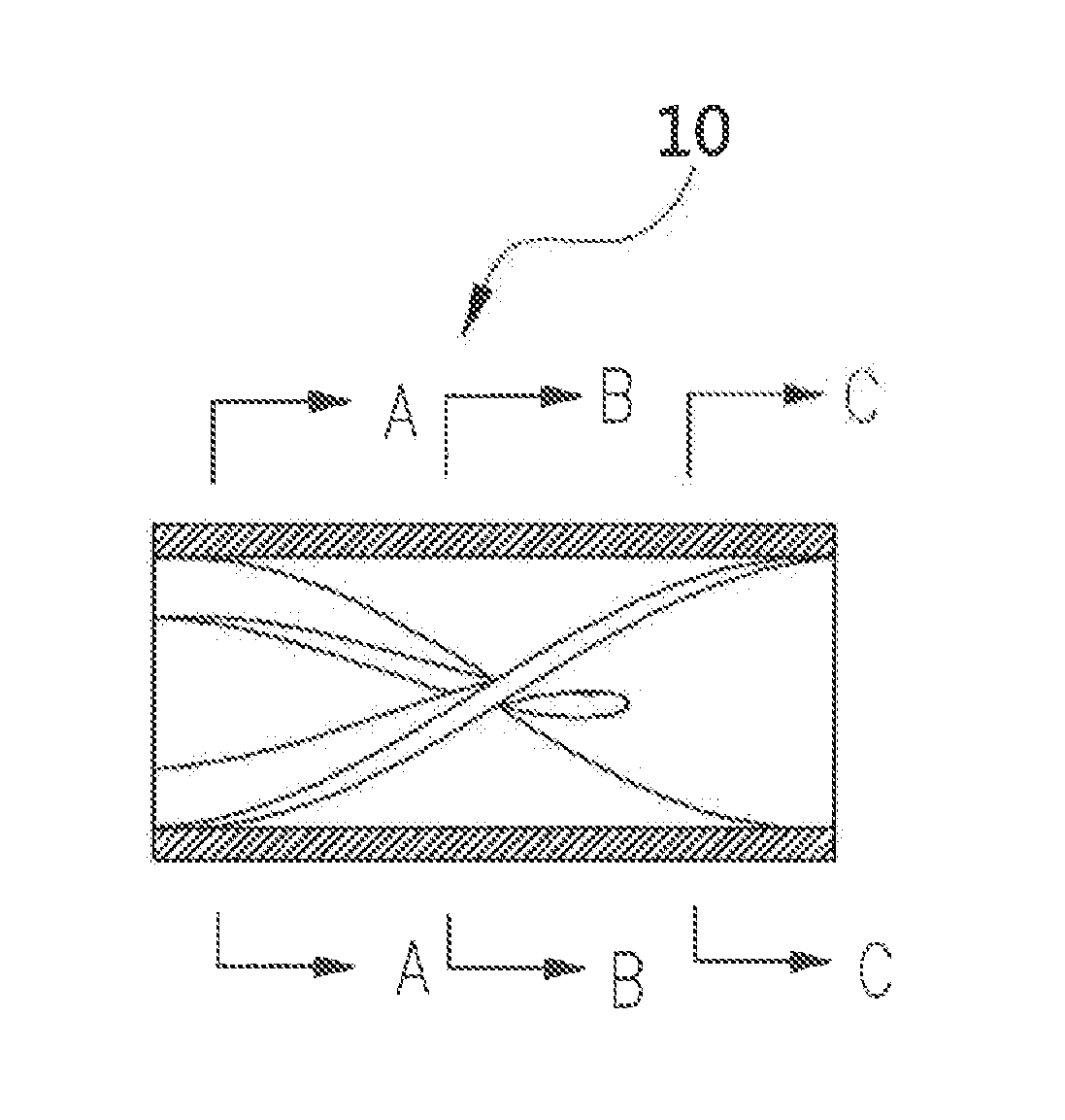
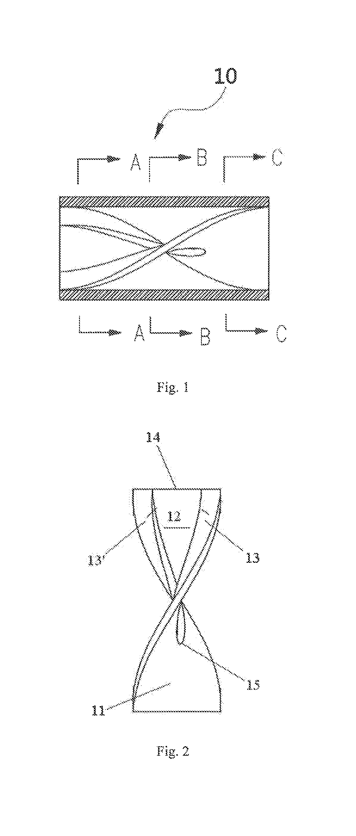
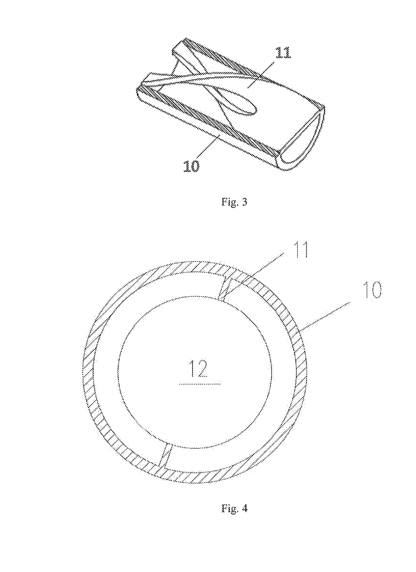
[0038]The radiant coil of the cracking furnace is arranged with 6 heat transfer tubes 10 with twisted baffles as indicated in FIG. 2. The inner diameter of each of the heat transfer tubes 10 is 51 mm. The ratio of the x-axis component of the curvature radius change rate of the curve segment to the inner diameter of the heat transfer tube is 0.6:1; the ratio of the y-axis component of the curvature radius change rate of the curve segment to the inner diameter of the heat transfer tube is 0.6:1; and the ratio of the z-axis component of curvature radius change rate of the curve segment to the inner diameter of the heat transfer tube is 2:1. The twisted baffles 11 and 11′ respectively have a twist angle of 180° and a twist ratio of 2.5. The distance between two adjacent heat transfer tubes 10 is 50 times as large as the inner diameter of the heat transfer tube. Experiments have found that the heat transfer load of the radiant coil is 1,278.75 KW and the pressure drop is 70,916.4 Pa.


PUM


Abstract

The present disclosure relates to a heat transfer tube and a racking furnace using the heat transfer tube. The heat transfer tube comprises a twisted baffle arranged in an inner wall of the tube, said twisted baffle extending spirally along an axial direction of the heat transfer tube. The twisted baffle is provided with a non-through gap extending along an axial direction of the heat transfer tube from an end to the other end of the twisted baffle. The heat transfer tube and cracking furnace according to the present disclosure have good heat transfer effects and small pressure loss.

Description

[0001]This application claims benefit of priority under 35 U.S.C. §119 to Chinese Patent Application No. CN 201310512687.2, filed Oct. 25, 2013, the contents of which are also incorporated herein by references.TECHNICAL FIELD[0002]The present disclosure relates to a heat transfer tube which is especially suitable for a heating furnace. The present disclosure further relates to a cracking furnace using the heat transfer tube.TECHNICAL BACKGROUND[0003]Cracking furnaces, the primary equipment in the petrochemical industry, are mainly used for heating hydrocarbon material so as to achieve cracking reaction which requires a large amount of heat. Fourier's theorem says,qA=-ktywherein q is the heat transferred, A represents the heat transfer area, k stands for the heat transfer coefficient, and dt / dy is the temperature gradient. Taking a cracking furnace used in the petrochemical industry as an example, when the heat transfer area A (which is determined by the capacity of the cracking furn...

Claims


Application Information

Patent Timeline
Patent Type & Authority Applications(United States)
IPC IPC(8): F28F1/12F28F13/12
CPCF28F13/12F28F1/12C10G9/20F28F1/40F28F13/02F28D2021/0059F15D1/02F15D1/0005F28F2215/00F28F1/36F28F1/32
Inventor WANG, GUOQINGZHANG, LIJUNZHOU, XIANFENGLIU, JUNJIEDU, ZHIGUOZHANG, YONGGANGZHANG, ZHAOBINZHOU, CONG
Owner CHINA PETROCHEMICAL CORP
Why Eureka
Try Eureka