
Demulsification, dehydration and separation method of emulsion

A separation method and emulsion technology, which is applied in the field of demulsification and dehydration separation of emulsions, and can solve problems such as low speed, increased difficulty, unfavorable droplet coalescence, etc.

Active Publication Date: 2021-07-30
CHONGQING TECH & BUSINESS UNIV
View PDF19 Cites 1 Cited by
  • Summary
  • Abstract
  • Description
  • Claims
  • Application Information

AI Technical Summary

Problems solved by technology

[0003] However, it is difficult to effectively demulsify and dehydrate the emulsion with a single treatment method. For example, the electric field method refers to placing the emulsion in a high-voltage AC or DC electric field In the process, the effect of the electric field on the water droplets is used to reduce the strength of the emulsion interface film, prompting the water droplets to collide and merge into large-particle water droplets, so that the water phase and the oil phase are separated; but with the increase of the water content of the emulsion, in the emulsion It is more difficult to establish a certain electric field strength between the electrodes in the liquid, which leads to certain limitations of the electric field method
The cyclone separation method refers to the high-speed rotation of the emulsion, using the different densities of the oil phase and the water phase to generate different centrifugal forces, thereby realizing the separation of the water phase and the oil phase; although the centrifuge can make the emulsion reach a higher speed, but Maintenance is relatively difficult, so the current cyclone centrifugation method mostly uses a hydrocyclone, which uses hydrocyclone to separate the water phase and the oil phase, but the rotational speed of the hydrocyclone is lower than that provided by the centrifuge, resulting in separation less effective
[0004]So at present, a variety of processing methods are used for joint processing or coupled and integrated units for processing to obtain better separation effects, among which, electric field method and cyclone centrifugation method The combination method is more common, that is, to couple the electric field with the cyclone centrifugal field, so that the two complement each other, so as to achieve the effect of increasing the droplet size and rapid and effective separation, and greatly improving the demulsification and dehydration efficiency of the emulsion. However, at present, the cyclone in the coupling device of the electric field and the swirling centrifugal field adopts a direct-facing double-cone section structure transition connection between the coaxial swirl chamber and the bottom flow tube of different diameters, see Figure 1, the transition of the double-cone section is gradient-like and non-smooth connection, patented CN201811485648.7 An electrostatic cyclone demulsification device and its application are also involved, but facing the double cone section area will cause the vibration of the flow field inside the cyclone, resulting in an unstable flow field, which is not conducive to the coalescence of droplets. Thus affecting the separation effect and separation efficiency

Method used


Image

  • Demulsification, dehydration and separation method of emulsion
  • Demulsification, dehydration and separation method of emulsion
  • Demulsification, dehydration and separation method of emulsion

Examples


Embodiment

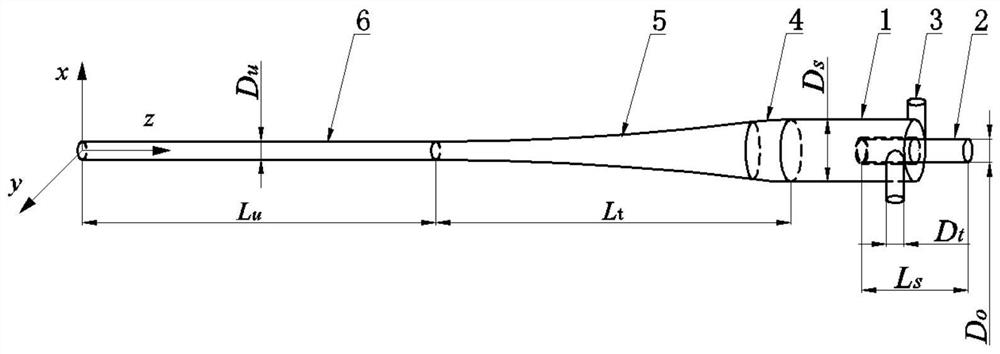
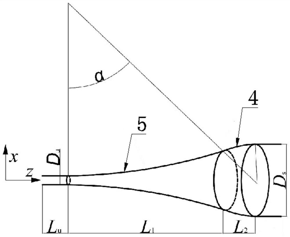
[0057] See Figure 2 - Figure 4 , An emulsion is broken-milk dehydrating separation method, including a cyclone, the cyclone comprising a swirl chamber with a cylindrical section and a bottom pipe with the swirl chamber, one end of the swirl chamber is closed and The inlet tube and an overflow tube coaxial with the swirl chamber are connected to the circumference of the inner wall of the swirl chamber, and the number of inlet tubes is two, two inlet tubes. The axis center of the swirl chamber is symmetrical.

[0058] The overflow tube is insulated through the closed end of the swirl chamber and in the inner end and the swirl chamber; the other end of the swirl chamber toward the bottom pipe and communicates with the bottom pipe through the coaxial smooth transition pipe section; the wall of the swirl chamber And overflow tubes are electrically conductive materials.

[0059] On the axial cross section of the swirl chamber, the inner wall of the smooth transition tube includes a conv...


PUM

PropertyMeasurementUnit
Kinematic viscosityaaaaaaaaaa

Abstract

The invention relates to a demulsification, dehydration and separation method for emulsion. A hydrocyclone comprises a rotational flow chamber and an underflow pipe, the closed end of the rotational flow chamber is connected with an inlet pipe and an overflow pipe, the inlet pipe is tangent to and communicates with the circumferential inner wall of the rotational flow chamber, the overflow pipe penetrates through the closed end of the rotational flow chamber in an insulated mode to communicate with the interior of the rotational flow chamber, the other end of the rotational flow chamber communicates with the underflow pipe through a smooth transition pipe section, and both the rotational flow chamber and the overflow pipe are conductive. The method comprises the following steps that firstly, the emulsion is pretreated; then the overflow pipe faces upwards and is electrically connected with the positive electrode of a high-voltage pulse power supply, the rotational flow chamber is grounded; and then the pretreated emulsion is continuously input into the rotational flow chamber from the inlet pipe. According to the hydrocyclone used in the demulsification and dehydration method, the smooth transition pipe section is adopted for transition between the rotational flow chamber and the underflow pipe, so that the turbulence intensity in the hydrocyclone is reduced, a flow field is promoted to be stable, under the action of an electric field, coalescence of water drops in the emulsion is facilitated, the particle size is increased, and therefore the separation effect and the separation efficiency are improved.

Description

Technical field [0001] The present invention is a technical field of liquid physical separation, and more particularly to an emulsion of the umuli dehydrating separation method. Background technique [0002] In the field of petrochemical, oilfield mining, resource environment and other engineering, the oil-in-water type (W / O) emulsion is more common, and it is a relatively critical process as a comparative process, such as oil entering refining. Dehydration treatment and dehydration treatment in the process of waste oil resources. At present, the emulsion dehydration treatment method has physical law, chemical method, and biological law, etc., the most common treatment method is physical method, physical method including electric field method, swirling centrifugation, gravity settlement method, and vacuum heating method. [0003] However, it is difficult to effectively dendrify the emulsion by a single treatment method, for example, an electric field method refers to the use of...

Claims


Application Information

Patent Timeline
IPC IPC(8): B04C5/04B04C5/081B04C9/00
CPCB04C5/04B04C5/081B04C9/00B04C2009/001
Inventor 龚海峰邱值彭烨陈凌余保
Owner CHONGQING TECH & BUSINESS UNIV
Learn More