
Liquid cooled reductant delivery unit for automotive selective catalytic reduction systems

a technology of automotive selective catalytic reduction and reductant, which is applied in the direction of engines, mechanical equipment, machines/engines, etc., can solve the problems of difficult treatment, long light-off times, and high nitrogen oxide emissions of lean-burn engines, and achieves sufficient structural robustness and improves assembly corrosion resistance.

Inactive Publication Date: 2015-03-05
CONTINENTAL AUTOMOTIVE SYST INC
View PDF6 Cites 22 Cited by
  • Summary
  • Abstract
  • Description
  • Claims
  • Application Information

AI Technical Summary

Benefits of technology

The present invention is a device designed to deliver a reductant while actively cooling it. The device is designed to be strong and resistant to corrosion, even if the coolant media used is not correct for the base injector. The technical effect is to provide a reliable and durable reductant delivery system with improved cooling capabilities.

Problems solved by technology

Lean-burn engines exhibit high levels of nitrogen oxide emissions (NOx), that are difficult to treat in oxygen-rich exhaust environments characteristic of lean-burn combustion.
This results in relatively low temperatures at the SCR catalyst, longer light-off times, and low conversion efficiency of the NOx.
However, this close placement may result in a high ambient thermal environment for the injector.

Method used


Image

  • Liquid cooled reductant delivery unit for automotive selective catalytic reduction systems
  • Liquid cooled reductant delivery unit for automotive selective catalytic reduction systems
  • Liquid cooled reductant delivery unit for automotive selective catalytic reduction systems

Examples


Embodiment Construction

[0018]The following description of the preferred embodiment(s) is merely exemplary in nature and is in no way intended to limit the invention, its application, or uses.

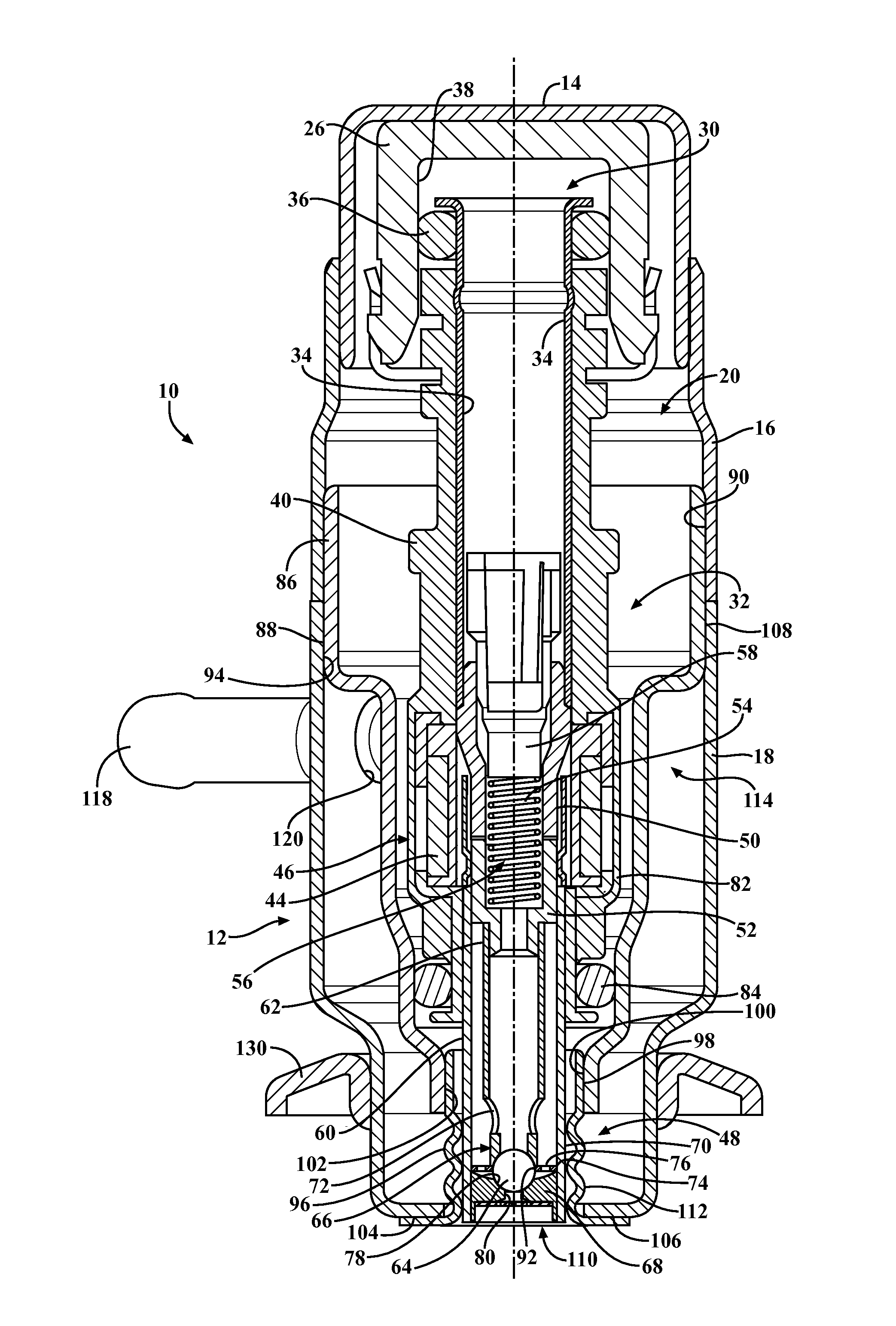
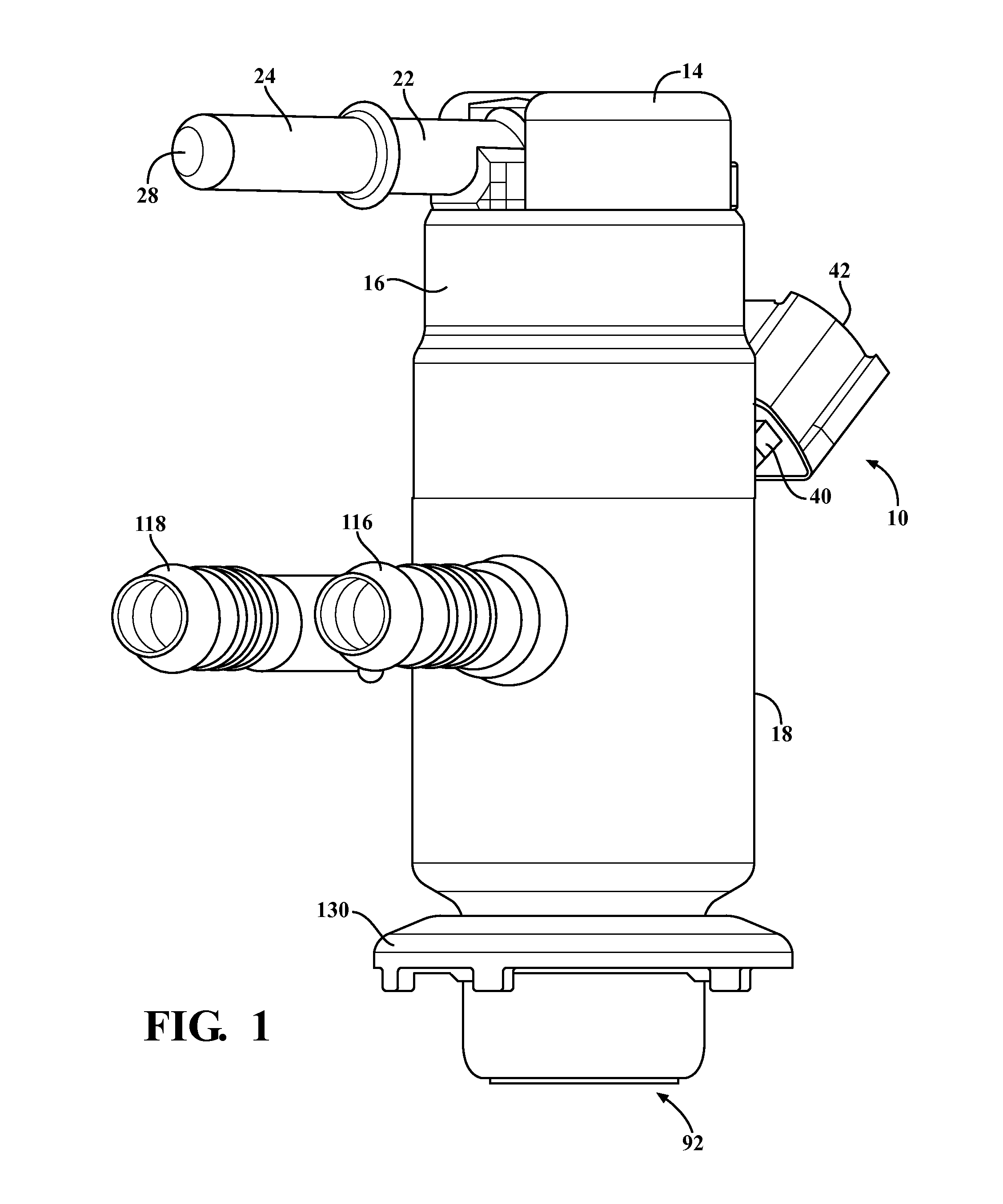
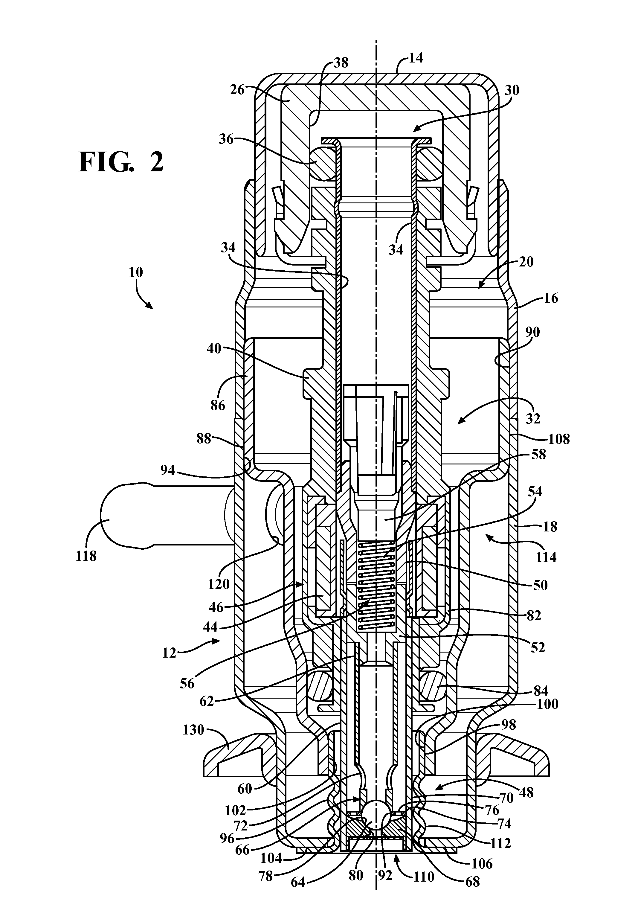
[0019]Referring to the FIGS. 1-3, an embodiment of a reductant delivery unit for an automotive selective catalytic reduction (SCR) system with active cooling is shown generally at 10. The reductant delivery unit 10 includes an outer shell or casing, shown generally at 12, and the shell 12 includes a retaining cap 14, which is connected to an upper shield 16, and a lower shield 18, which is also connected to the upper shield 16. The retaining cap 14 and the shields 16,18 when connected together form a cavity, shown generally at 20, in which various components are disposed.

[0020]The cap 14 at least partially surrounds a hydraulic connector 22. The hydraulic connector 22 has an inlet pipe 24, and an inlet cup 26, which in this embodiment are integrally formed together, but it is within the scope of the invention that the...


PUM


Abstract

A reductant delivery unit having active cooling which is constructed to have sufficient structural robustness, and to improve corrosion resistance of the assembly, where an attack on the base injector is conceivable with the use of incorrect coolant media. The reductant delivery unit has an upper shield, a lower shield connected to the upper shield, and an inner sleeve. The reductant delivery unit also includes a lower sleeve connected to the inner sleeve and the lower shield. A liquid cooling cavity is formed by the connection between the inner sleeve and the lower shield, the lower sleeve and the lower shield, and the lower sleeve and the inner sleeve. Coolant flows into the liquid cooling cavity to provide a cooling function to an injector partially located within the inner sleeve, and a corrugated portion of the lower sleeve transfers heat away from at least a portion of the injector.

Description

FIELD OF THE INVENTION[0001]The invention relates generally to providing active cooling for a reductant delivery unit for an automotive selective catalytic reduction system.BACKGROUND OF THE INVENTION[0002]New emissions legislation in Europe and North America is driving the implementation of new exhaust after treatment systems, particularly for lean-burn technologies such as compression-ignition (diesel) engines, and stratified-charge spark-ignited engines (usually with direct injection) that are operating under lean and ultra-lean conditions. Lean-burn engines exhibit high levels of nitrogen oxide emissions (NOx), that are difficult to treat in oxygen-rich exhaust environments characteristic of lean-burn combustion. Exhaust after treatment technologies are currently being developed that treat NOx under these conditions.[0003]One of these technologies includes a catalyst that facilitates the reactions of ammonia (NH3) with the exhaust nitrogen oxides (NOx) to produce nitrogen (N2) a...

Claims


Application Information

Patent Timeline
IPC IPC(8): F01N3/20
CPCF01N3/208F01N3/2066F01N2610/02F01N2610/11F01N2610/1453Y02T10/12
Inventor BUGOS, STEPHEN C.VAN VUUREN, WILLEM NICOLAAS
Owner CONTINENTAL AUTOMOTIVE SYST INC
Learn More