
Combined Heat and Power Technology for Natural Gas Liquefaction Plants

a technology of natural gas liquefaction and heat generation, which is applied in the direction of liquefaction, machines/engines, lighting and heating apparatus, etc., can solve the problems of large synchronous motors, less reliable and demanding more control equipment, and large induction motors that can operate at high speeds, etc., to reduce fuel gas consumption, reduce greenhouse gas emissions, and optimize the overall production facility

Inactive Publication Date: 2014-09-18
APACHE CORPORATION
View PDF7 Cites 12 Cited by
  • Summary
  • Abstract
  • Description
  • Claims
  • Application Information

AI Technical Summary

Benefits of technology

The present invention provides a system and method to recover and utilize waste heat generated in LNG facilities, reducing fuel gas consumption and greenhouse gas emissions. A dedicated onsite power unit can generate power to supply all the plant's electrical demand, and the separation of the power facility from the liquefaction area allows for more efficient operation. The waste heat can also be used for process heating, reducing the demand for fuel. Natural gas or other supplemental gas fuel can be burned to provide additional energy for power production and heating services. The method also reduces greenhouse gas emissions by utilizing waste heat from gas turbines to produce steam, which can then be used to power processes used in the production of liquefied natural gas.

Problems solved by technology

Additional compression power is typically supplied through use of gas turbine generators or other external sources, with the help of large synchronous motors with load commutated inverter (“LCI”) drives, which require additional fuel gas consumption leading to higher operating costs and higher plant greenhouse gas emissions.
Synchronous motors are larger, more expensive, less reliable and require more control equipment than induction motors, but large induction motors that can operate at high speeds are not known in the art.

Method used


Image

  • Combined Heat and Power Technology for Natural Gas Liquefaction Plants
  • Combined Heat and Power Technology for Natural Gas Liquefaction Plants
  • Combined Heat and Power Technology for Natural Gas Liquefaction Plants

Examples


Embodiment Construction

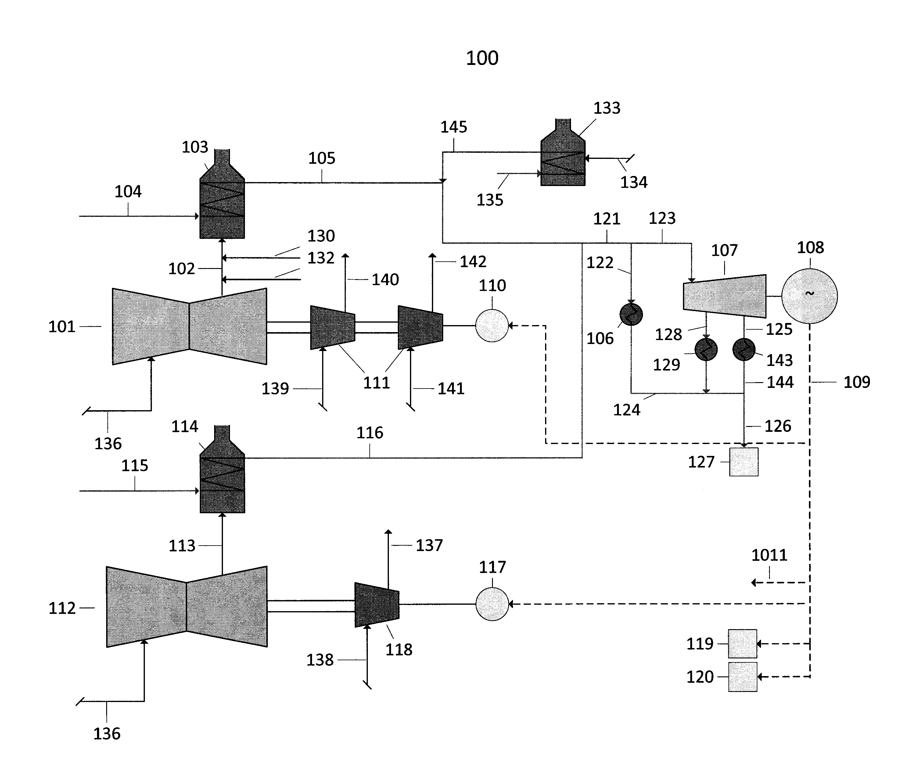
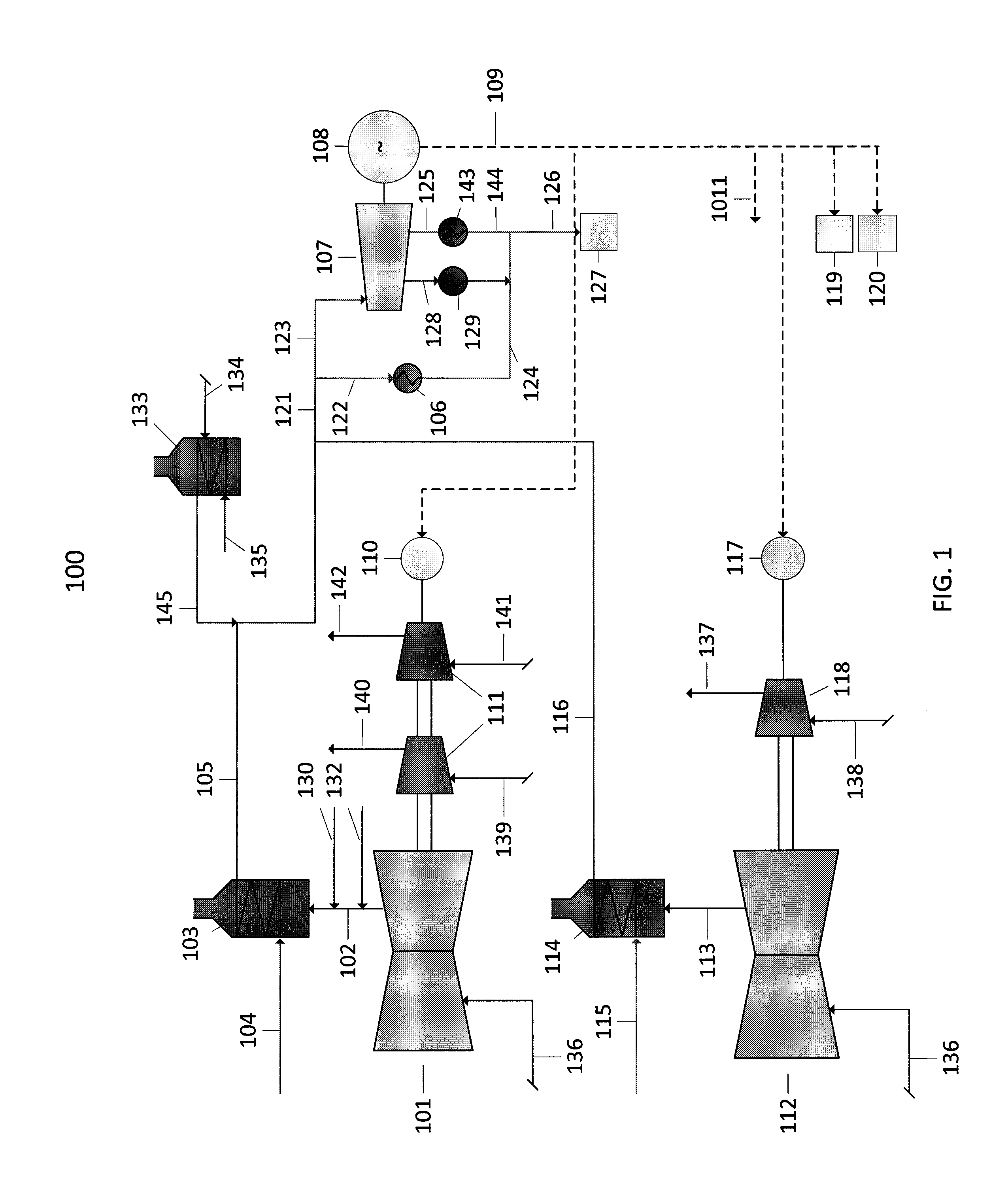
[0026]FIG. 1 is a schematic drawing of a LNG facility waste heat recovery system 100 in accordance with one embodiment of the present invention. Waste heat recovery system 100 comprises a first gas turbine 101 connected to a first plurality of refrigeration compressors 111, although in other embodiments (not shown) the first gas turbine 101 can be connected to a single refrigeration compressor 111. In general refrigeration compressors 111 are rotary type, either centrifugal or axial, although other types and configurations can find utility in further aspects of the present disclosure. The first gas turbine 101 produces hot exhaust gas that travels through a first exhaust line 102 to a first heat recovery steam generator (“HRSG”) 103, which takes boiler feed water from first water line 104 and produces steam that travels through first steam line 105. The HRSG 103 may be installed vertically or horizontally, and may produce steam at one or more pressure levels. The heat recovery devic...


PUM


Abstract

Systems and methods for the generation of liquid natural gas (“LNG”) are provided.

Description

CROSS-REFERENCE TO RELATED APPLICATION[0001]Not ApplicableSTATEMENT REGARDING FEDERALLY SPONSORED RESEARCH OR DEVELOPMENT[0002]Not ApplicableTHE NAMES OF THE PARTIES TO A JOINT RESEARCH AGREEMENT[0003]Not ApplicableINCORPORATION-BY-REFERENCE OF MATERIAL SUBMITTED ON A COMPACT DISC[0004]Not ApplicableBACKGROUND OF THE INVENTION[0005]1. Field of the Invention[0006]This invention relates generally to systems and methods for the generation of liquefied natural gas (“LNG”).[0007]2. Description of the Related Art[0008]Natural gas can be converted to liquefied natural gas (“LNG”) by cooling it to about −161° C., depending on the exact composition of the natural gas, which reduces its volume to about 1 / 600th of its original value. This reduction in volume can make transportation more economical. For example, the LNG can be transferred to a cryogenic storage tank located on an ocean-going ship. Once the ship arrives at its destination, the LNG can be offloaded to a regasification facility, i...

Claims


Application Information

Patent Timeline
Patent Type & Authority Applications(United States)
IPC IPC(8): F01K23/06
CPCF01K23/06F01K3/24F01K17/025F01K23/064F25J2240/70F25J1/0242F25J1/0283F25J1/0284F01K23/10F25J1/0022F25J1/0287F25J1/029F25J2205/66F25J2220/64F25J2220/68F25J2240/82F25J2245/90Y02E20/14Y02P80/15F25J2230/22F25J2230/60
Inventor SHAPOT, BRETAGRAWAL, DEVENDRARAY, JOHNSOUTHWARD, ERIC
Owner APACHE CORPORATION
Learn More