
Universal power supply system with load isolating and voltage enhance device

a power supply system and load isolating technology, applied in the direction of power to the power outlet, propulsion by capacitors, battery/cells, etc., can solve the problems of high battery cost, large space requirements for battery stacking, and speed and distance range limitations of electric vehicles, so as to improve speed and ampere hours rating, the effect of increasing the input voltag

Inactive Publication Date: 2014-09-11
ARUMUGAM RAJENDRA BABU +2
View PDF2 Cites 5 Cited by
  • Summary
  • Abstract
  • Description
  • Claims
  • Application Information

AI Technical Summary

Benefits of technology

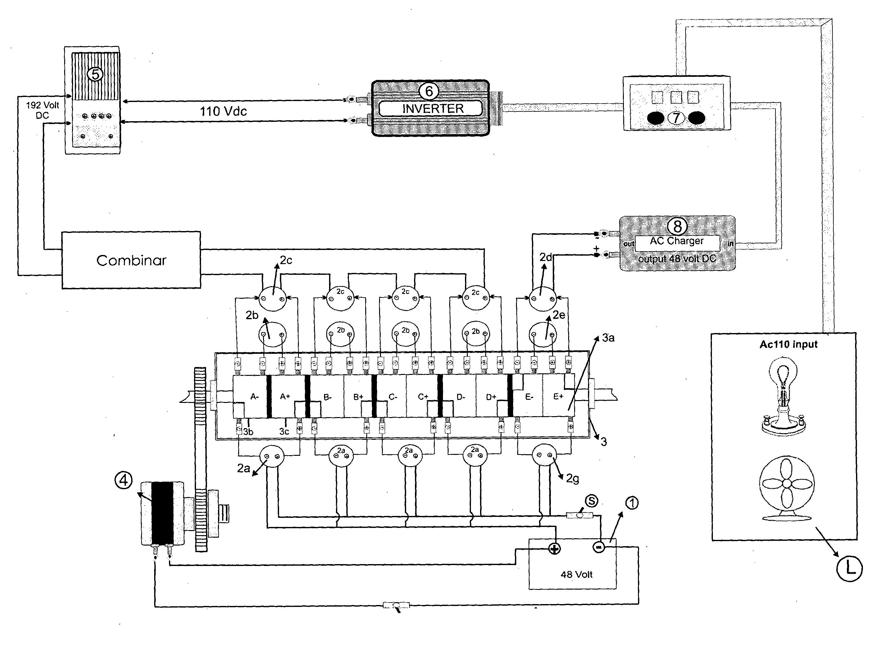
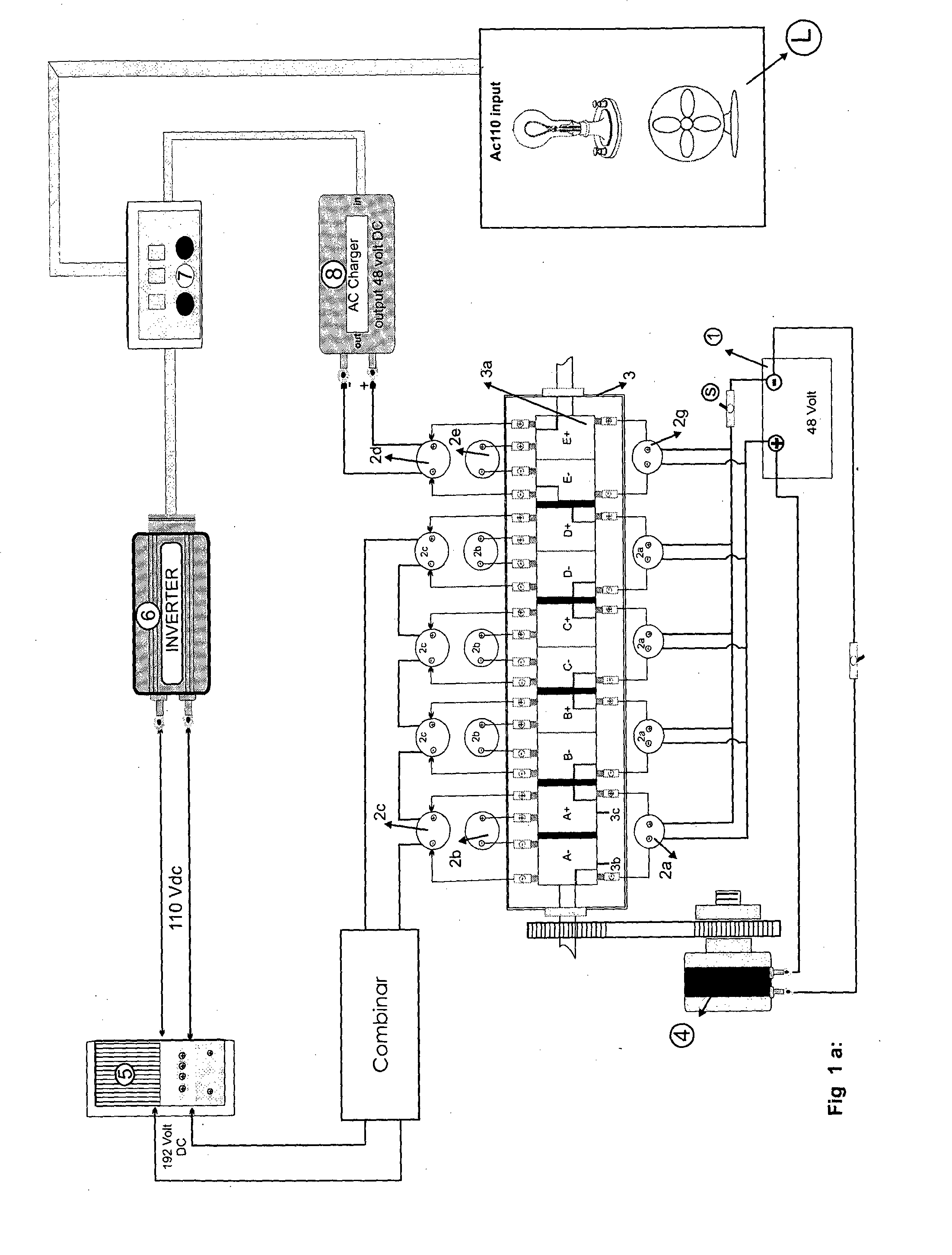
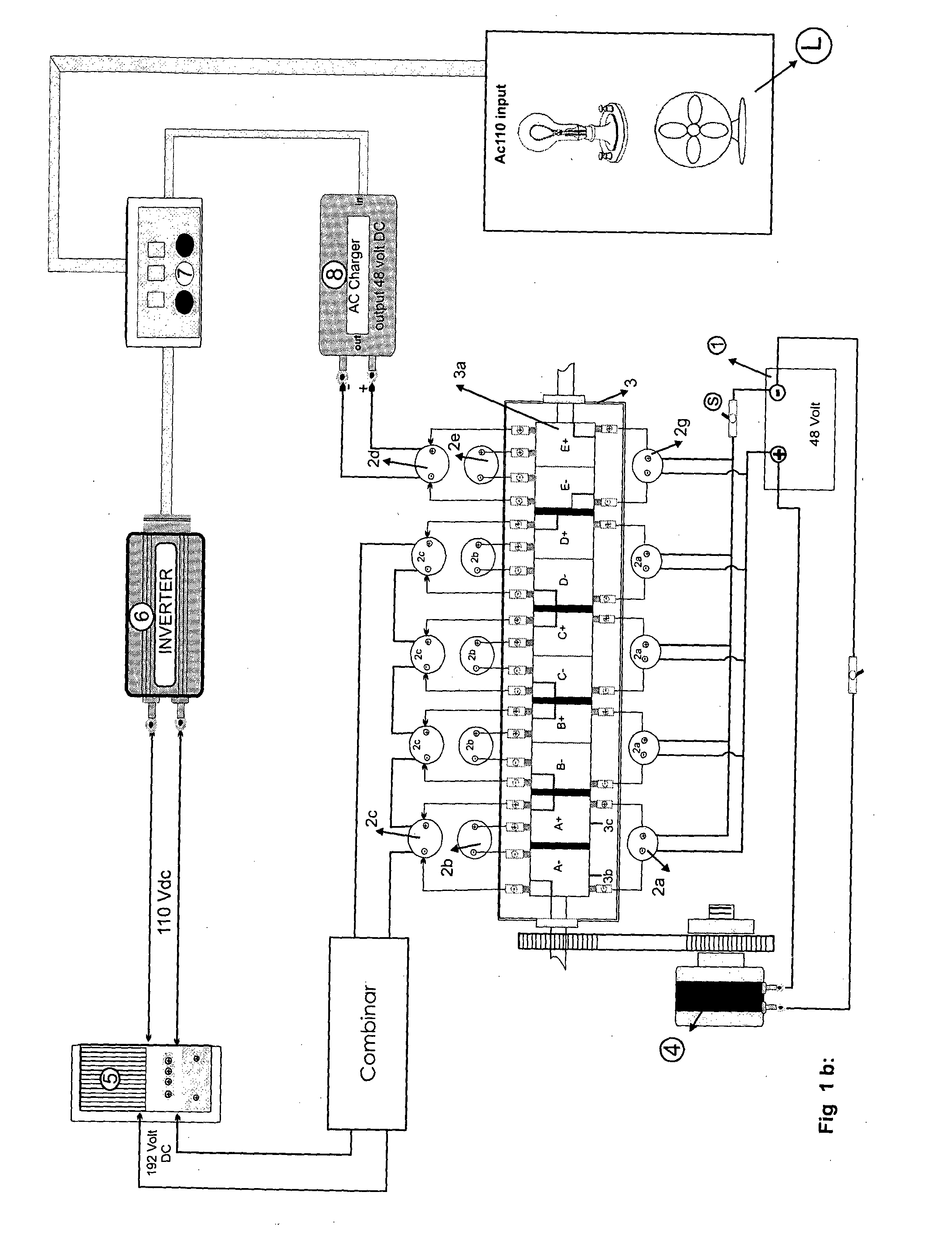
The invention is a power supply system for electric vehicles that uses a low input voltage from a power supply unit to yield a higher output voltage by maintaining the energy rating of the storage device. The system achieves complete isolation between the load and input power supply unit, reducing the burden on the recharging unit and allowing for reutilization of the output power. The system utilizes a plurality of capacitors and batteries to achieve both high voltage and high Ah capacity, improving speed and mileage requirements. The input battery or plurality of batteries connected in parallel along with the input capacitors is the input voltage source. The system includes a single input battery with low voltage rating, which is increased through the use of capacitors and an intermediate section to achieve the required operating voltage of the load. The system is designed to enable easy replacement of depleted batteries and is cost-effective and energy-efficient.

Problems solved by technology

The electric vehicles suffer from drawbacks of speed and distance range limitations.
In order to achieve higher speed and more mileage, large battery packs are adopted as power source, but this leads to disadvantages like high cost of batteries and large space requirements for battery stacking and also increase in the overall weight of the vehicle.
The recharging power obtained from using the regenerative energy is not adequate to make up the loss in the batteries utilized for driving the load.
Similarly, the use of large solar energy panels and bulky wind generators in wind tunnel systems always proved to be not feasible because more recharging power is required by the large battery packs and more space requirements for installation of the above systems.
While carrying out the recharging of the batteries during movement of the vehicle, the load like drive motor creates an impact on the output of the recharging unit like wind generators thereby affecting the online charging of the batteries.
It is quite difficult to charge a battery at the same moment it is discharging to a load as the recharger unit is directly affected by the load.
This has led to the problems in real-time charging of the battery packs to achieve the desired distance range.
The drawbacks in an electric vehicle includes speed and distance limitations, usage of large battery packs occupies more space and increases weight of the vehicle, usage of large solar panels and / or bulky wind generators for recharging of the batteries, problems in real-time recharging of the batteries due to impact of the load on the recharging unit during simultaneous charging and discharging.
This requirement leads to drawback of more space requirement and also increase in weight and cost of the system / vehicle.

Method used


Image

  • Universal power supply system with load isolating and voltage enhance device
  • Universal power supply system with load isolating and voltage enhance device
  • Universal power supply system with load isolating and voltage enhance device

Examples


first embodiment

[0016]In case a single battery with full load Ah requirement is not feasible, another embodiment of the power supply system shall comprise of single power supply unit having plurality of batteries, designed as accumulator unit, connected in parallel. The said batteries are of minimum voltage and minimum Ah rating, but are connected in parallel to satisfy the full load current requirement. The other constructional features and functions of the power supply system remain the same as

third embodiment

[0017]In case of vehicle movement in a traffic congested area, there is provided an option for running the vehicle without engaging the recharging unit. This leads to third embodiment of the invention, in which the power supply system without the recharging unit is employed. The other constructional features and functions of the power supply system remains the same as anyone of the above embodiments.

[0018]Another important embodiment of the invention is a power supply system with a single battery or plurality of batteries in parallel as an input battery, having a recycling circuit which recycles the output power to top up the input source. The intermediate section is such that input stage and the output stage are completely isolated which makes the recycling possible. The recycling circuit utilizes either a portion of the output power from the power supply unit before feeding the load or the power regenerated from the load. The recycling circuit includes suitable charger circuit and...


PUM


Abstract

This invention relates to power supply system having recharging unit with load isolation and its method of operation. The power supply unit has one or more energy storage device and such energy storage device is of low voltage rating when compared with the operating voltage of the load. The power supply units when operated through an intermediate section and an output combiner, due to alternative parallel and series connections of capacitors supplies to the load an enhanced voltage as required by the load with complete isolation between the recharging unit of the system and load. The recharging unit supplies the recharging voltage to the input battery whenever the input battery is isolated from the load. Due to which, the energy storage devices serves for large distance range and better speed range in case of electric vehicles.

Description

FIELD OF INVENTION[0001]This invention relates to a modified electrical power supply system with recharging unit / recycling unit with complete isolation between source and the load.[0002]This invention is utilized as a power supply in any device or system which is operated electrically. The invention is also suitable for DC or AC load applications. This invention is more relevant for non-conventional energy generating units and electric vehicle applications. For the purpose of clarity and conciseness, in the following description reference is mainly with respect to an electric vehicle with wind generators as the recharging unit. This is without any limitation to the scope of the invention.BACKGROUND OF THE INVENTION[0003]The electric vehicles suffer from drawbacks of speed and distance range limitations. To obtain better speed performance and mileage, the voltage and energy capacity of the batteries are important. In order to achieve higher speed and more mileage, large battery pack...

Claims


Application Information

Patent Timeline
IPC IPC(8): H02J7/00
CPCH02J7/0068B60L1/006B60L50/40B60L50/52B60L53/14B60L2210/40B60L2240/12Y02T10/70Y02T10/7072Y02T10/72Y02T90/14Y02T90/12
Inventor ARUMUGAM, RAJENDRA BABU
Owner ARUMUGAM RAJENDRA BABU
Learn More